

2011 EMC Directory & Design Guide - Interference Technology
2011 EMC Directory & Design Guide - Interference Technology
2011 EMC Directory & Design Guide - Interference Technology

Create successful ePaper yourself
Turn your PDF publications into a flip-book with our unique Google optimized e-Paper software.
testing & test equipment<br />
O n t h e R a di at i o n Pat t e rns of C o mmon <strong>EMC</strong> A n t e nn a s<br />
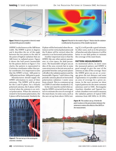
Figure 7. Model of a log periodic in front of a metal<br />
top bench (the ground is metallic).<br />
Figure 8. Results for the model in Figure 7. Notice that the radiation<br />
is deflected by the presence of the metallic top bench.<br />
(HPBW) is also known as the 3dB beam<br />
width. The HPBW is given in degrees<br />
and it describes the arc of the angle<br />
between the two points to the side of<br />
the point of highest radiation that are<br />
3dB lower in radiated power. Figure<br />
6 shows the half power beamwidth<br />
for the pattern shown in Figure 5. For<br />
clarity, the pattern is represented in<br />
Cartesian coordinates rather than polar<br />
coordinates. It is important to note<br />
that the HPBW is from -3dB point to<br />
-3dB point not from -3dB point to peak.<br />
Manufacturers should supply the<br />
HPBW information to users of their<br />
antennas. The HPBW will be given<br />
for the E and H plane. For a linearly<br />
polarized antenna, the E plane will be<br />
vertical when the antenna is on vertical<br />
polarization. When the antenna is<br />
rotated to horizontal polarization, the<br />
E plane will be horizontal. Similarly the<br />
H plane will be horizontal when the antenna<br />
is set for vertical polarization and<br />
the H plane will be vertical when the<br />
antenna is on horizontal polarization.<br />
Another important issue is that the<br />
HPBW, like any other pattern parameter,<br />
is a free space, far field parameters.<br />
The beamwidth will give you an<br />
idea of the area covered, but in some<br />
cases structures in the test area such as<br />
grounded benches and ground planes<br />
will affect the radiation pattern and the<br />
beamwidth. Figures 7 and 8 show a log<br />
periodic antenna placed on horizontal<br />
polarization radiation 1 meter away<br />
from a bench. This is a common set up<br />
in CISPR 25 and other standards [2-4].<br />
So the user must be careful when using<br />
the HPBW extracted from the pattern<br />
to estimate the area of coverage of<br />
the main beam. In some cases, such as<br />
the new set up from above 1GHz test-<br />
ing [5], it will provide a good estimate.<br />
In other cases, such as in the presence<br />
of benches and other features, it will be<br />
better to use field probes to estimate<br />
the coverage of the main beam.<br />
PAtteRN MEASUREMentS<br />
As mentioned above, in most cases<br />
the measured pattern and HPBW is<br />
good enough to give the user of the<br />
antenna an idea of the coverage. Since<br />
the HPBW gives you an arc or coverage<br />
given the test distance and some<br />
trigonometry it is possible to estimate<br />
an area of coverage for a given antenna.<br />
In the next sections we show<br />
typical patterns for the most common<br />
antennas used in <strong>EMC</strong>. Rectangular<br />
Anechoic chamber and Tapered Anechoic<br />
chambers were used to measure<br />
the radiation pattern of typical <strong>EMC</strong><br />
antennas from 400 MHz to 18 GHz.<br />
Figure 10. The outdoor set up. A ferrite tile<br />
patch is place on the ground plane between the<br />
antennas to reduce the effects of the OATS on<br />
the measurement.<br />
Figure 9. The test set up in the rectangular<br />
anechoic chamber.<br />
40 interference technology emc <strong>Directory</strong> & design guide <strong>2011</strong>


![[ thursday ] morning sessions 8:30 am-noon - Interference Technology](https://img.yumpu.com/23176841/1/190x247/-thursday-morning-sessions-830-am-noon-interference-technology.jpg?quality=85)

