

2011 EMC Directory & Design Guide - Interference Technology
2011 EMC Directory & Design Guide - Interference Technology
2011 EMC Directory & Design Guide - Interference Technology

Create successful ePaper yourself
Turn your PDF publications into a flip-book with our unique Google optimized e-Paper software.
JAVOR<br />
Between 0 and d/2 along the rod antenna, the electric<br />
field from the wire above ground contributes an induced potential<br />
on the rod between 0 and d/2 of -3.6 uV (equation 6f).<br />
Between 0 and d/2 along the rod antenna, the electric<br />
field from the image wire contributes a potential given by<br />
equation 6h of -15.4 uV (equation 6h).<br />
Thus the total potential induced from 0 to 5 cm is -19 uV.<br />
Equation 6g yields a potential of 938 uV induced between<br />
5 cm and 1.04 meters due to the field from the wire above<br />
ground.<br />
Equation 6i yields a potential of -1283 uV induced between<br />
5 cm and 1.04 meters due to the field from the image<br />
wire.<br />
The sum of the potentials over the whole rod is -364 uV,<br />
or 51.2 dBuV. Per above discussion, this means the effective<br />
field intensity is 51.2 dBuV/m and the unloaded potential<br />
appearing at the base of the rod to be amplified is 45.2 dBuV.<br />
Because the Ailtech 95010-1 rod antenna used in this effort<br />
loads the open-circuit potential by 2 dB, then provides 0 dB<br />
voltage gain, the output to an EMI receiver would be 43.2<br />
dBuV, or -63.8 dBm.<br />
This is what we expect to measure when configured as<br />
in Figure 3a. We also have independent verification that<br />
this value is in the right ballpark. The rationale appendix<br />
of MIL-STD-461D/E/F cites a relationship between rf potential<br />
on a 2.5 meter wire below 30 MHz and the radiated<br />
quasi-static electric field intensity. The transfer function is<br />
stated to be that the electric field intensity is 40 dB down<br />
from the rf potential. In the set-up used in this investigation,<br />
the wire is only 1.1 meter long, therefore we expect the<br />
transfer function to be 4.25 dB less efficient based on the<br />
wire length dependence of equation 1a, or 44.25 dB down.<br />
Starting with a wire potential of 97 dBuV, we expect a field<br />
intensity of 52.75 dBuV/m. The 51.2 dBuV/m calculation<br />
agrees within 1.55 dB.<br />
A similar calculation is performed when analyzing rod<br />
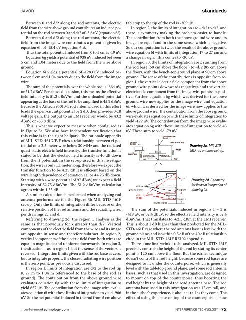
antenna performance for the Figure 3b MIL-STD-461F<br />
set-up. Only the limits of integration differ because of the<br />
relative position of the rod antenna and the radiating wire,<br />
per drawings 2c and d.<br />
Referring to drawing 2d, the region 1 analysis is the<br />
same as that previously for x greater than d/2. Vertical<br />
components of the electric field from the wire and its image<br />
are opposite in sense and therefore subtract. In region 2,<br />
vertical components of the electric field from both wires are<br />
equal in magnitude and reinforce downwards. In region 3,<br />
the situation is as in region 1, but the sense of the vectors is<br />
reversed. Integration limits given with the rod base as zero,<br />
but to integrate properly, the closest radiating wire position<br />
is the zero point, as previously discussed.<br />
In region 1, limits of integration are d/2 to the rod tip<br />
(0.27 m to 1.04 m referenced to the base of the rod as<br />
ground). The contribution from the above ground wire<br />
evaluates equation 6g with these limits of integration to<br />
yield 657 uV. The contribution from the image wire evaluates<br />
equation 6i with these limits of integration to yield -966<br />
uV. So the net potential induced in the rod from 5 cm above<br />
standards<br />
tabletop to the tip of the rod is -309 uV.<br />
In region 2, the limits of integration are –d/2 to d/2, and<br />
there is symmetry making the problem easier to handle.<br />
The contribution from both the above ground wire and its<br />
image are equal and in the same sense, which is negative.<br />
So our computation is twice the result of the above ground<br />
wire equation 6f with limits of integration 17 to 27 cm and<br />
a change in sign. This comes to -30 uV.<br />
In region 3, the limits of integration are x running from<br />
the rod base (68 cm above the floor ) to -d/2 (85 cm above<br />
the floor), with the bench-top ground plane at 90 cm above<br />
ground. The sense of the contributions is opposite from region<br />
1: the vertical electric field component from the above<br />
ground wire points downwards (negative), and the vertical<br />
electric field component from the image wire points up, positive.<br />
Further, equation 6g which was derived for the above<br />
ground wire now applies to the image wire, and equation<br />
6i, which was derived for the image wire now applies to the<br />
above ground wire. The contribution from the above ground<br />
wire evaluates equation 6i with these limits of integration to<br />
yield -122 uV. The contribution from the image wire evaluates<br />
equation 6g with these limits of integration to yield 43<br />
uV. These sum to yield -79 uV.<br />
Drawing 2c. MIL-STD-<br />
461F rod antenna set-up.<br />
Drawing 2d. Geometry<br />
for limits of integration of<br />
drawing 2c.<br />
The sum of the potentials induced in regions 1 – 3 is<br />
-418 uV, or 52.4 dBuV, so the effective field intensity is 52.4<br />
dBuV/m. That translates to -62.5 dBm at the EMI receiver.<br />
This is about 1 dB higher than that predicted for the MIL-<br />
STD-461E case where the rod antenna base is level with the<br />
ground plane, and is within 0.5 dB of the 40 dB relationship<br />
cited in the MIL-STD-461F RE102 appendix.<br />
There is one final wrinkle to be analyzed. MIL-STD-461F<br />
precisely controls the height of the rod by stating its center<br />
point is 120 cm above the floor. But the earlier technique<br />
doesn’t control the rod height, because some rod bases are<br />
designed to fit under the counterpoise, which is generally<br />
level with the tabletop ground plane, and some rod antenna<br />
bases, such as that used in this investigation, are designed<br />
to mount on top of the counterpoise, thus boosting the<br />
rod height by the height of the road antenna base. The rod<br />
antenna base used in this investigation was 12 cm tall, and<br />
in the author’s experience, is about as tall as they come. The<br />
effect of using this base on top of the counterpoise is now<br />
interferencetechnology.com interference technology 73


![[ thursday ] morning sessions 8:30 am-noon - Interference Technology](https://img.yumpu.com/23176841/1/190x247/-thursday-morning-sessions-830-am-noon-interference-technology.jpg?quality=85)

