

2011 EMC Directory & Design Guide - Interference Technology
2011 EMC Directory & Design Guide - Interference Technology
2011 EMC Directory & Design Guide - Interference Technology

Create successful ePaper yourself
Turn your PDF publications into a flip-book with our unique Google optimized e-Paper software.
testing & test equipment<br />
O n t h e R a di at i o n Pat t e rns of C o mmon <strong>EMC</strong> A n t e nn a s<br />
Figure 2. A pyramidal horn radiating; a sample of an impedance transition between the<br />
transmission line and free space.<br />
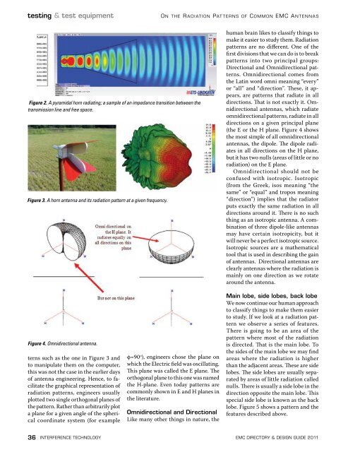
Figure 3. A horn antenna and its radiation pattern at a given frequency.<br />
human brain likes to classify things to<br />
make it easier to study them. Radiation<br />
patterns are no different. One of the<br />
first divisions that we can do is to break<br />
patterns into two principal groups:<br />
Directional and Omnidirectional patterns.<br />
Omnidirectional comes from<br />
the Latin word omni meaning “every”<br />
or “all” and “direction”. These, it appears,<br />
are patterns that radiate in all<br />
directions. That is not exactly it. Omnidirectional<br />
antennas, which radiate<br />
omnidirectional patterns, radiate in all<br />
directions on a given principal plane<br />
(the E or the H plane. Figure 4 shows<br />
the most simple of all omnidirectional<br />
antennas, the dipole. The dipole radiates<br />
in all directions on the H plane,<br />
but it has two nulls (areas of little or no<br />
radiation) on the E plane.<br />
Omnidirectional should not be<br />
confused with isotropic. Isotropic<br />
(from the Greek, isos meaning “the<br />
same” or “equal” and tropos meaning<br />
“direction”) implies that the radiator<br />
puts exactly the same radiation in all<br />
directions around it. There is no such<br />
thing as an isotropic antenna. A combination<br />
of three dipole-like antennas<br />
may have certain isotropicity, but it<br />
will never be a perfect isotropic source.<br />
Isotropic sources are a mathematical<br />
tool that is used in describing the gain<br />
of antennas. Directional antennas are<br />
clearly antennas where the radiation is<br />
mainly on one direction as we rotate<br />
around the antenna.<br />
Figure 4. Omnidirectional antenna.<br />
terns such as the one in Figure 3 and<br />
to manipulate them on the computer,<br />
this was not the case in the earlier days<br />
of antenna engineering. Hence, to facilitate<br />
the graphical representation of<br />
radiation patterns, engineers usually<br />
plotted two single orthogonal planes of<br />
the pattern. Rather than arbitrarily plot<br />
a plane for a given angle of the spherical<br />
coordinate system (for example<br />
φ=90 o ), engineers chose the plane on<br />
which the Electric field was oscillating.<br />
This plane was called the E plane. The<br />
orthogonal plane to this one was named<br />
the H-plane. Even today patterns are<br />
commonly shown in E and H planes in<br />
the literature.<br />
Omnidirectional and Directional<br />
Like many other things in nature, the<br />
Main lobe, side lobes, back lobe<br />
We now continue our human approach<br />
to classify things to make them easier<br />
to study. If we look at a radiation pattern<br />
we observe a series of features.<br />
There is going to be an area of the<br />
pattern where most of the radiation<br />
is directed. That is the main lobe. To<br />
the sides of the main lobe we may find<br />
areas where the radiation is higher<br />
than the adjacent areas. These are side<br />
lobes. The side lobes are usually separated<br />
by areas of little radiation called<br />
nulls. There is usually a side lobe in the<br />
direction opposite the main lobe. This<br />
special side lobe is known as the back<br />
lobe. Figure 5 shows a pattern and the<br />
features described above.<br />
36 interference technology emc <strong>Directory</strong> & design guide <strong>2011</strong>


![[ thursday ] morning sessions 8:30 am-noon - Interference Technology](https://img.yumpu.com/23176841/1/190x247/-thursday-morning-sessions-830-am-noon-interference-technology.jpg?quality=85)

