

2011 EMC Directory & Design Guide - Interference Technology
2011 EMC Directory & Design Guide - Interference Technology
2011 EMC Directory & Design Guide - Interference Technology

You also want an ePaper? Increase the reach of your titles
YUMPU automatically turns print PDFs into web optimized ePapers that Google loves.
filters<br />
<br />
<br />
<br />
<br />
<br />
<br />
<br />
<br />
<br />
<br />
<br />
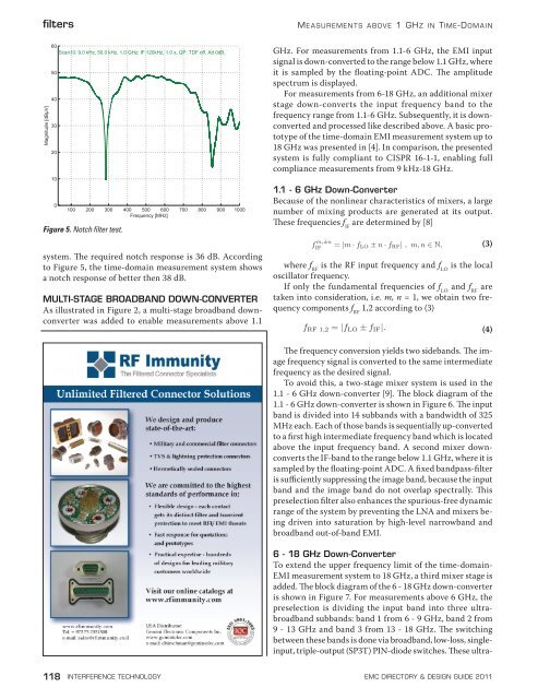
Figure 5. Notch filter test.<br />
system. The required notch response is 36 dB. According<br />
to Figure 5, the time-domain measurement system shows<br />
a notch response of better then 38 dB.<br />
MULTI-STAGE BROADBAND DOWN-CONVERTER<br />
As illustrated in Figure 2, a multi-stage broadband downconverter<br />
was added to enable measurements above 1.1<br />
M e a s ur e m e n t s a b o v e 1 GHz in Time-Domain<br />
GHz. For measurements from 1.1-6 GHz, the EMI input<br />
signal is down-converted to the range below 1.1 GHz, where<br />
it is sampled by the floating-point ADC. The amplitude<br />
spectrum is displayed.<br />
For measurements from 6-18 GHz, an additional mixer<br />
stage down-converts the input frequency band to the<br />
frequency range from 1.1-6 GHz. Subsequently, it is downconverted<br />
and processed like described above. A basic prototype<br />
of the time-domain EMI measurement system up to<br />
18 GHz was presented in [4]. In comparison, the presented<br />
system is fully compliant to CISPR 16-1-1, enabling full<br />
compliance measurements from 9 kHz-18 GHz.<br />
1.1 - 6 GHz Down-Converter<br />
Because of the nonlinear characteristics of mixers, a large<br />
number of mixing products are generated at its output.<br />
These frequencies f IF<br />
are determined by [8]<br />
f m,±n<br />
IF<br />
= |m · f LO ± n · f RF | , m, n ∈ N, (3)<br />
where f RF<br />
is the RF input frequency and f LO<br />
is the local<br />
oscillator frequency.<br />
If only the fundamental frequencies of f LO<br />
and f RF<br />
are<br />
taken into consideration, i.e. m, n = 1, we obtain two frequency<br />
components f RF<br />
1,2 according to (3)<br />
f RF 1,2 = |f LO ± f IF |. (4)<br />
The frequency conversion yields two sidebands. The image<br />
frequency signal is converted to the same intermediate<br />
frequency as the desired signal.<br />
To avoid this, a two-stage mixer system is used in the<br />
1.1 - 6 GHz down-converter [9]. The block diagram of the<br />
1.1 - 6 GHz down-converter is shown in Figure 6. The input<br />
band is divided into 14 subbands with a bandwidth of 325<br />
MHz each. Each of those bands is sequentially up-converted<br />
to a first high intermediate frequency band which is located<br />
above the input frequency band. A second mixer downconverts<br />
the IF-band to the range below 1.1 GHz, where it is<br />
sampled by the floating-point ADC. A fixed bandpass-filter<br />
is sufficiently suppressing the image band, because the input<br />
band and the image band do not overlap spectrally. This<br />
preselection filter also enhances the spurious-free dynamic<br />
range of the system by preventing the LNA and mixers being<br />
driven into saturation by high-level narrowband and<br />
broadband out-of-band EMI.<br />
6 - 18 GHz Down-Converter<br />
To extend the upper frequency limit of the time-domain-<br />
EMI measurement system to 18 GHz, a third mixer stage is<br />
added. The block diagram of the 6 - 18 GHz down-converter<br />
is shown in Figure 7. For measurements above 6 GHz, the<br />
preselection is dividing the input band into three ultrabroadband<br />
subbands: band 1 from 6 - 9 GHz, band 2 from<br />
9 - 13 GHz and band 3 from 13 - 18 GHz. The switching<br />
between these bands is done via broadband, low-loss, singleinput,<br />
triple-output (SP3T) PIN-diode switches. These ultra-<br />
118 interference technology emc <strong>Directory</strong> & design guide <strong>2011</strong>


![[ thursday ] morning sessions 8:30 am-noon - Interference Technology](https://img.yumpu.com/23176841/1/190x247/-thursday-morning-sessions-830-am-noon-interference-technology.jpg?quality=85)

