

2011 EMC Directory & Design Guide - Interference Technology
2011 EMC Directory & Design Guide - Interference Technology
2011 EMC Directory & Design Guide - Interference Technology

You also want an ePaper? Increase the reach of your titles
YUMPU automatically turns print PDFs into web optimized ePapers that Google loves.
K e e bl e r, Berge r<br />
radiated emissions<br />
slated for use in the new plants will provide much needed<br />
emissions guidance and aid in the prevention of future EMI<br />
problems.<br />
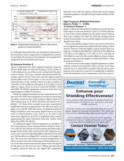
Figure 3. Radiated electric field spectra, 10 kHz to 1 GHz, antenna<br />
position 2 in control room (Unit 1).<br />
3). Although these limit lines are intended to determine if<br />
the emissions from a single piece of equipment or system<br />
are too high, the emissions from both the ACS and the DCS<br />
equipment do exceed these limit lines.<br />
2) Antenna Position 2<br />
Figure 3 illustrates the final radiated emissions trace for<br />
electric fields taken at Antenna Position 2 from 10 kHz to<br />
1 GHz adjacent to one of the system cabinets for the plant<br />
control system. This trace contains the data for both the<br />
analog control system (red trace) and the digital control<br />
system (blue trace). From Figure 2, one can see that a few<br />
characteristics of the analog control are that it peaks at<br />
1.04 MHz at 99.3 dBμV/m and again at 4.55 MHz at 88.5<br />
dBμV/m. Again, these two traces cross the NUREG 1.180<br />
and EPRI TR-102323 equipment emissions limit lines for<br />
high frequency radiated emissions.<br />
While the radiated emissions in the region between 139<br />
kHz and 2.61 MHz have dropped as a result of converting<br />
the plant control system from analog to digital, there are<br />
other regions (e.g., A, B, and C) that have increased in amplitude.<br />
132 These three example areas have experienced<br />
amplitude increases ranging from a few dB to as much as<br />
high as over 40 dB. With the nature of radiated emissions<br />
being cumulative with increasing digital devices in areas<br />
such as Control Rooms, areas such as A, B, and C will<br />
experience significant growth in amplitude more closely<br />
approaching the plant emissions limit line (yellow line)<br />
defined by EPRI TR-102323.<br />
As additional digital control equipment is installed in<br />
the Control Room, these emissions levels will grow. Moreover,<br />
with the new advanced nuclear plants presently under<br />
design (some under early construction), I&C engineers can<br />
expect new concerns regarding higher emissions levels and<br />
new EMI problems as digital I&C controls are brought on<br />
line. This is an area that deserves careful consideration in<br />
efforts to lower the risk of allowing an EMI problem to occur<br />
in the fleet of advanced nuclear plants built and placed<br />
on the grid over the next ten years. Efforts put into place<br />
to gather emissions data for new digital I&C equipment<br />
High-Frequency Radiated Emissions –<br />
Electric Fields: 1 – 6 GHz<br />
1) Antenna Position 1<br />
Figure 4 illustrates the radiated emissions trace for electric<br />
fields taken at Antenna Position 1 from 1 to 6 GHz adjacent<br />
to one of the system cabinets for the plant control system.<br />
This trace contains the data for both the analog control<br />
system (red and blue traces) and the digital control system<br />
(purple trace only).<br />
From red and blue (upper) traces, one can see that there<br />
are no significant peaks associated with the analog control<br />
system. However, with the digital control system there are<br />
peaks at 1.35 GHz at 49.9 dBμV/m, 1.88 GHz at 50.5 dBμV/m,<br />
1.92 GHz at 53.4 dBμV/m, 2.41 GHz at 76.3, 2.46 GHz at<br />
54.4 dBμV/m, and 5.82 GHz at 60.6 dBμV/m. Some of these<br />
spectral components are higher at Antenna Position 1 than<br />
at Antenna Position 2.<br />
From increases in the usage of digital equipment in other<br />
mission-critical environments where surveys have been<br />
carried out, it is reasonable to predict that the above components<br />
will experience a growth in amplitude in addition<br />
to the development of new components with faster proces-<br />
interferencetechnology.com interference technology 97


![[ thursday ] morning sessions 8:30 am-noon - Interference Technology](https://img.yumpu.com/23176841/1/190x247/-thursday-morning-sessions-830-am-noon-interference-technology.jpg?quality=85)

