

2011 EMC Directory & Design Guide - Interference Technology
2011 EMC Directory & Design Guide - Interference Technology
2011 EMC Directory & Design Guide - Interference Technology

You also want an ePaper? Increase the reach of your titles
YUMPU automatically turns print PDFs into web optimized ePapers that Google loves.
standards<br />
O n t h e N at ur e a nd Us e of t h e 1.04 m El e c t ric Fiel d Probe<br />
Figure 1a.<br />
MIL-I-6181B<br />
use of 1.04 m<br />
rod antenna<br />
(ca. 1953).<br />
Figure 1b. Recreation of Figure 1a.<br />
made the measurement more susceptible<br />
to test chamber resonances. There<br />
was good rationale for the changes, but<br />
measurement accuracy suffered. The<br />
counterpoise isolation proposed herein<br />
restores the integrity of the measurement<br />
set-up as originally configured.<br />
The field sensing mechanism of the<br />
rod antenna is the effective potential<br />
difference between the rod base (counterpoise)<br />
and the rod tip. Since the<br />
rod's potential is measured relative to<br />
the counterpoise's potential, anything<br />
that affects the counterpoise's potential<br />
affects the measurement. This is the<br />
key point ignored by all present standards.<br />
Weston’s critique [5] does not<br />
ignore the effect of the counterpoise,<br />
but that effort promotes the use of the<br />
grounded counterpoise, which references<br />
[1] – [3] as well as this effort show<br />
to be quite detrimental. Of all present<br />
standards, only MIL-STD-461F (2007)<br />
attempts to provide some control of the<br />
counterpoise potential. In so doing,<br />
MIL-STD-461F provides dampening of<br />
resonances occurring above 20 MHz.<br />
Theoretical 1.04 m rod performance,<br />
actual performance of the traditional<br />
and the MIL-STD-461F implementation,<br />
and the proposed counterpoise<br />
isolation technique are compared<br />
herein. It is important to realize that<br />
“traditional” does not imply correct.<br />
In [3], evolution of the use of the 1.04<br />
m rod antenna from the earliest days<br />
is explained and it is shown that what<br />
is now considered “traditional,” due to<br />
common use since 1970, is in fact an<br />
aberration.<br />
BACKGROUND<br />
Analytical modeling and chamber testing<br />
described herein are based on a one<br />
meter long cable suspended 5 cm above<br />
a ground plane 10 cm back from the<br />
edge of the plane as shown in Figures<br />
2 and 3. A level of -10 dBm was applied<br />
from 2 – 32 MHz driving a 50 Ohm termination.<br />
The -10 dBm level converts to<br />
70.7 mV in a 50 ohm system. All data<br />
plots are 2-32 MHz. The test chamber<br />
size was 8’ x 8’ x 8’, unlined. The lowest<br />
chamber resonance can be calculated<br />
from a commonly used equation to be<br />
87 MHz, which is almost three times<br />
the highest measurement frequency<br />
of interest (30 MHz). Thus the fact<br />
that the measurements were made in<br />
a hybrid shield/screen room with no<br />
absorber lining does not affect measurement<br />
integrity. The rod antenna<br />
used was the Ailtech 95010-1, with a<br />
constant antenna factor of 8 dB/m from<br />
10 kHz to 40 MHz. Data plots included<br />
herein are uncorrected raw antennainduced<br />
potentials. The correlation of<br />
this data with analytical predictions<br />
is not obscured by any hidden factors.<br />
The rod antenna network was also used<br />
to measure counterpoise potentials<br />
with respect to the chamber floor. For<br />
this measurement, the network has 0<br />
dB voltage gain and no correction factor<br />
is necessary for the actual voltage.<br />
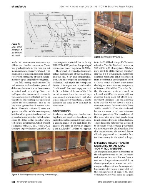
Figure 2. Radiating structure, following common usage.<br />
EFFECTIVE FIELD STRENGTH<br />
MEASURED BY AN IDEAL<br />
1.04 M ROD ANTENNA<br />
An analytical derivation is presented of<br />
the voltage developed on the 1.04 meter<br />
rod antenna due to radiation from a<br />
one meter long cable suspended 5 cm<br />
above a ground plane, spaced one meter<br />
away, as in Figures 2 and 3a. A separate<br />
but similar derivation is provided for<br />
the configuration of Figure 3b. The<br />
computed values will serve as targets<br />
68 interference technology emc <strong>Directory</strong> & design guide <strong>2011</strong>


![[ thursday ] morning sessions 8:30 am-noon - Interference Technology](https://img.yumpu.com/23176841/1/190x247/-thursday-morning-sessions-830-am-noon-interference-technology.jpg?quality=85)

