

2011 EMC Directory & Design Guide - Interference Technology
2011 EMC Directory & Design Guide - Interference Technology
2011 EMC Directory & Design Guide - Interference Technology

Create successful ePaper yourself
Turn your PDF publications into a flip-book with our unique Google optimized e-Paper software.
testing & test equipment<br />
Troubleshooting Radiated Emissions<br />
resonate strongly at multiples of a quarter wavelength. For<br />
example, a 1m long cable has a full-wave resonance of 300<br />
MHz, but may also radiate strongly at 150 and 75 MHz.<br />
Slots or seams of 8 to 15 cm may resonate in the area of 500<br />
to 800 MHz. As a general rule of thumb, radiating cables<br />
or chassis slots of 1/ 20th wavelength or greater, start to<br />
become significant radiating elements (or antennas) for RE.<br />
Figure 3. Examples of commercial E- and H-field probes from Beehive<br />
Electronics.<br />
Figure 4. Examples of homemade H-field probes.<br />
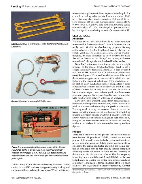
Figure 5. I made my own broadband preamp using a Mini-Circuits<br />
model ZX60-3018G-S. It is powered it with two 6V Duracell #28A<br />
batteries, which happen to fit in a standard “AA” battery holder. The<br />
amplifier covers 20 to 3000 MHz at 20 dB gain and is used to boost the<br />
probe signals.<br />
rial (example, 4.7 for FR4 circuit boards). However, typical<br />
cables, such as USB or video, are approximately 1m long and<br />
can be considered as being in free space. Wires or slots may<br />
USEFUL TOOLS<br />
Antennas<br />
The antenna you select should ideally be somewhere near<br />
resonance for the frequencies of concern, however, it’s not<br />
really that critical for troubleshooting purposes. So long<br />
as the antenna is fixed in length and fixed in place on the<br />
bench, you’ll receive consistent results. During troubleshooting,<br />
it’s more important to know whether the fix is<br />
“better” or “worse” or “no change” and as long as the test<br />
setup doesn’t change, the results should be believable.<br />
Now, <strong>EMC</strong> antennas are not inexpensive, as you might<br />
imagine, so for general troubleshooting, I tend to use a<br />
couple inexpensive television antennas - a pair of “rabbit<br />
ears” and a UHF “bowtie” (with TV balun to match 50-ohm<br />
coax). See Figure 2. If the workbench is wooden, I’ll extend<br />
the antenna to approximate resonance (if possible) and tape<br />
it down to the bench with duct tape. If the bench is metallic,<br />
I’ll find a non-conductive support and position it some<br />
distance away from the bench. I usually use a test distance<br />
of about a meter, but as long as you can see the product’s<br />
harmonics on a spectrum analyzer, you’ll be able to determine<br />
your progress. Sometimes I need to insert a low-noise<br />
wide-band preamp between antenna and analyzer.<br />
Now, obviously, ambient signals from broadcast radio,<br />
television mobile phones and two-way radio services will<br />
tend to interfere with observing the product harmonics.<br />
You may need to bring the antenna closer or set up the<br />
troubleshooting measurement in a basement or building<br />
interior away from outside windows. I usually record the<br />
known harmonics of concern using an H-field probe or by<br />
bringing the measurement antenna in close and then try<br />
to characterize them in relation to other nearby ambient<br />
signals.<br />
Probes<br />
There are a variety of useful probes that may be used to<br />
troubleshoot RE problems; E-field, H-field and current<br />
probes. 1 All are easily made in the lab or are available from<br />
several manufacturers. An E-field probe may be made by<br />
extending the center conductor about 0.5 cm from a section<br />
of semi-rigid coax or high-quality flexible coax; then<br />
attaching a coax connector to the other end. Shorting of<br />
the probe to circuit traces may be avoided by wrapping<br />
insulating tape around the end. A useful H-field probe may<br />
be fashioned by looping the center conductor around and<br />
soldering it to the shield to form a small loop of 0.5 to 5 cm in<br />
diameter - the larger the loop, the more sensitivity. A better<br />
1<br />
Probe manufacturers include Fischer Custom Communications, Beehive<br />
Electronics or Teseq.<br />
16 interference technology emc <strong>Directory</strong> & design guide <strong>2011</strong>


![[ thursday ] morning sessions 8:30 am-noon - Interference Technology](https://img.yumpu.com/23176841/1/190x247/-thursday-morning-sessions-830-am-noon-interference-technology.jpg?quality=85)

