

2011 EMC Directory & Design Guide - Interference Technology
2011 EMC Directory & Design Guide - Interference Technology
2011 EMC Directory & Design Guide - Interference Technology

You also want an ePaper? Increase the reach of your titles
YUMPU automatically turns print PDFs into web optimized ePapers that Google loves.
filters<br />
M e a s ur e m e n t s a b o v e 1 GHz in Time-Domain<br />
µ<br />
<br />
<br />
<br />
<br />
<br />
<br />
<br />
<br />
<br />
<br />
yielding a total frequency shift of<br />
δf = 6 · 10 MHz = 60 MHz (9)<br />
for the 6th harmonic.<br />
CONCLUSION<br />
The theory and application of time-domain EMI measurement<br />
systems according to CISPR 16-1-1 have been presented.<br />
Such measurement systems allow to reduce test time, and<br />
to perform investigations of the emission of ISM equipment<br />
above 1 GHz. As such emission measurement systems allow<br />
for real-time measurements over large frequency bands, the<br />
non-stationary behavior of the electromagnetic interference<br />
can be measured and weighted.<br />
<br />
<br />
<br />
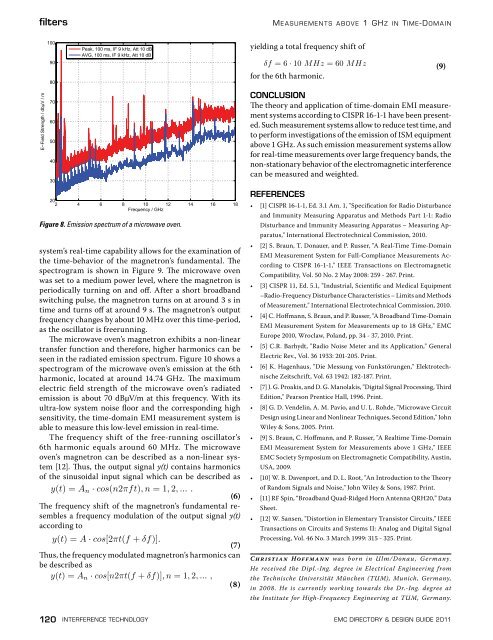
Figure 8. Emission spectrum of a microwave oven.<br />
system’s real-time capability allows for the examination of<br />
the time-behavior of the magnetron’s fundamental. The<br />
spectrogram is shown in Figure 9. The microwave oven<br />
was set to a medium power level, where the magnetron is<br />
periodically turning on and off. After a short broadband<br />
switching pulse, the magnetron turns on at around 3 s in<br />
time and turns off at around 9 s. The magnetron’s output<br />
frequency changes by about 10 MHz over this time-period,<br />
as the oscillator is freerunning.<br />
The microwave oven’s magnetron exhibits a non-linear<br />
transfer function and therefore, higher harmonics can be<br />
seen in the radiated emission spectrum. Figure 10 shows a<br />
spectrogram of the microwave oven’s emission at the 6th<br />
harmonic, located at around 14.74 GHz. The maximum<br />
electric field strength of the microwave oven’s radiated<br />
emission is about 70 dBμV/m at this frequency. With its<br />
ultra-low system noise floor and the corresponding high<br />
sensitivity, the time-domain EMI measurement system is<br />
able to measure this low-level emission in real-time.<br />
The frequency shift of the free-running oscillator’s<br />
6th harmonic equals around 60 MHz. The microwave<br />
oven’s magnetron can be described as a non-linear system<br />
[12]. Thus, the output signal y(t) contains harmonics<br />
of the sinusoidal input signal which can be described as<br />
y(t) = A n · cos(n2πft), n = 1, 2, ... .<br />
(6)<br />
The frequency shift of the magnetron’s fundamental resembles<br />
a frequency modulation of the output signal y(t)<br />
according to<br />
y(t) = A · cos[2πt(f + δf)].<br />
(7)<br />
Thus, the frequency modulated magnetron’s harmonics can<br />
be described as<br />
y(t) = A n · cos[n2πt(f + δf)], n = 1, 2, ... ,<br />
(8)<br />
REFERENCES<br />
• [1] CISPR 16-1-1, Ed. 3.1 Am. 1, "Specification for Radio Disturbance<br />
and Immunity Measuring Apparatus and Methods Part 1-1: Radio<br />
Disturbance and Immunity Measuring Apparatus – Measuring Apparatus,"<br />
International Electrotechnical Commission, 2010.<br />
• [2] S. Braun, T. Donauer, and P. Russer, "A Real-Time Time-Domain<br />
EMI Measurement System for Full-Compliance Measurements According<br />
to CISPR 16-1-1," IEEE Transactions on Electromagnetic<br />
Compatibility, Vol. 50 No. 2 May 2008: 259 - 267. Print.<br />
• [3] CISPR 11, Ed. 5.1, "Industrial, Scientific and Medical Equipment<br />
–Radio-Frequency Disturbance Characteristics – Limits and Methods<br />
of Measurement," International Electrotechnical Commission, 2010.<br />
• [4] C. Hoffmann, S. Braun, and P. Russer, "A Broadband Time-Domain<br />
EMI Measurement System for Measurements up to 18 GHz," <strong>EMC</strong><br />
Europe 2010, Wroclaw, Poland, pp. 34 - 37, 2010. Print.<br />
• [5] C.R. Barhydt, "Radio Noise Meter and its Application," General<br />
Electric Rev., Vol. 36 1933: 201-205. Print.<br />
• [6] K. Hagenhaus, "Die Messung von Funkstörungen," Elektrotechnische<br />
Zeitschrift, Vol. 63 1942: 182-187. Print.<br />
• [7] J. G. Proakis, and D. G. Manolakis, "Digital Signal Processing, Third<br />
Edition," Pearson Prentice Hall, 1996. Print.<br />
• [8] G. D. Vendelin, A. M. Pavio, and U. L. Rohde, "Microwave Circuit<br />
<strong>Design</strong> using Linear and Nonlinear Techniques, Second Edition," John<br />
Wiley & Sons, 2005. Print.<br />
• [9] S. Braun, C. Hoffmann, and P. Russer, "A Realtime Time-Domain<br />
EMI Measurement System for Measurements above 1 GHz," IEEE<br />
<strong>EMC</strong> Society Symposium on Electromagnetic Compatibility, Austin,<br />
USA, 2009.<br />
• [10] W. B. Davenport, and D. L. Root, "An Introduction to the Theory<br />
of Random Signals and Noise," John Wiley & Sons, 1987. Print.<br />
• [11] RF Spin, “Broadband Quad-Ridged Horn Antenna QRH20,” Data<br />
Sheet.<br />
• [12] W. Sansen, "Distortion in Elementary Transistor Circuits," IEEE<br />
Transactions on Circuits and Systems II: Analog and Digital Signal<br />
Processing, Vol. 46 No. 3 March 1999: 315 - 325. Print.<br />
Christian Hoffm ann was born in Ulm/Donau , Germany.<br />
He received the Dipl.-Ing. degree in Electrical Engineering from<br />
the Technische Universität München (TUM), Munich, Germany,<br />
in 2008. He is currently working towards the Dr.-Ing. degree at<br />
the Institute for High-Frequency Engineering at TUM, Germany.<br />
120 interference technology emc <strong>Directory</strong> & design guide <strong>2011</strong>


![[ thursday ] morning sessions 8:30 am-noon - Interference Technology](https://img.yumpu.com/23176841/1/190x247/-thursday-morning-sessions-830-am-noon-interference-technology.jpg?quality=85)

