

2011 EMC Directory & Design Guide - Interference Technology
2011 EMC Directory & Design Guide - Interference Technology
2011 EMC Directory & Design Guide - Interference Technology

Create successful ePaper yourself
Turn your PDF publications into a flip-book with our unique Google optimized e-Paper software.
S c h o e m a n, Ja k o bu s<br />
shielding / cables & connectors<br />
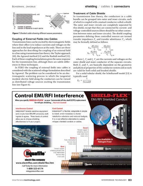
Figure 7. Braided cable showing different weave parameters.<br />
Coupling of External Fields into Cables<br />
Transmission lines can be excited by electromagnetic fields<br />
where their effect is to induce currents and voltages on the<br />
line and in the load impedances at the ends. There are three<br />
approaches for describing the coupling of an external field<br />
to a line using transmission line theory: the Taylor approach<br />
[10], the Agrawal method [11] and the Rashidi method [12].<br />
Each of these coupling formulations gives the same response<br />
for the transmission line, although there are subtle differences<br />
in these techniques.<br />
In FEKO the coupling of external fields into cables is<br />
considered with the scattered voltage formulation described<br />
by Agrawal. The problem can be considered to be an electromagnetic<br />
scattering process in which the tangential<br />
incident electric field along the conductors can be viewed<br />
as distributed voltage sources exciting the transmission<br />
line (see Figure 6).<br />
Treatment of Cable Shields<br />
In transmission line theory, the conductors in a cable<br />
bundle can be grouped into outer and inner circuits, each<br />
of which is coupled with a mutual conductor called a shield.<br />
The outer and inner circuits are completely separated by<br />
this shield, except that they are connected by current- and<br />
voltage-controlled sources (there should be no other connection<br />
between outer and inner circuits). The shield coupling<br />
parameters defining these controlled sources are termed<br />
transfer impedance Z T<br />
and transfer admittance Y T<br />
, which<br />
may be formally defined as follows<br />
where I s<br />
, V s<br />
and I i<br />
, V i<br />
are the currents and voltages on the<br />
outer shield and inner conductor of the separate circuits.<br />
Both Z T<br />
and Y T<br />
are basically dependent on the geometric<br />
and physical properties of the conductor system and as such<br />
are valid for both solid and braided shields.<br />
For a solid tubular shield, the Schelkunoff model [13] is<br />
typically used<br />
interferencetechnology.com interference technology 83


![[ thursday ] morning sessions 8:30 am-noon - Interference Technology](https://img.yumpu.com/23176841/1/190x247/-thursday-morning-sessions-830-am-noon-interference-technology.jpg?quality=85)

