

2011 EMC Directory & Design Guide - Interference Technology
2011 EMC Directory & Design Guide - Interference Technology
2011 EMC Directory & Design Guide - Interference Technology

You also want an ePaper? Increase the reach of your titles
YUMPU automatically turns print PDFs into web optimized ePapers that Google loves.
shielding / cables & connectors<br />
Num e ric a l S o l u t i o n of C o mpl e x <strong>EMC</strong> Probl e m s<br />
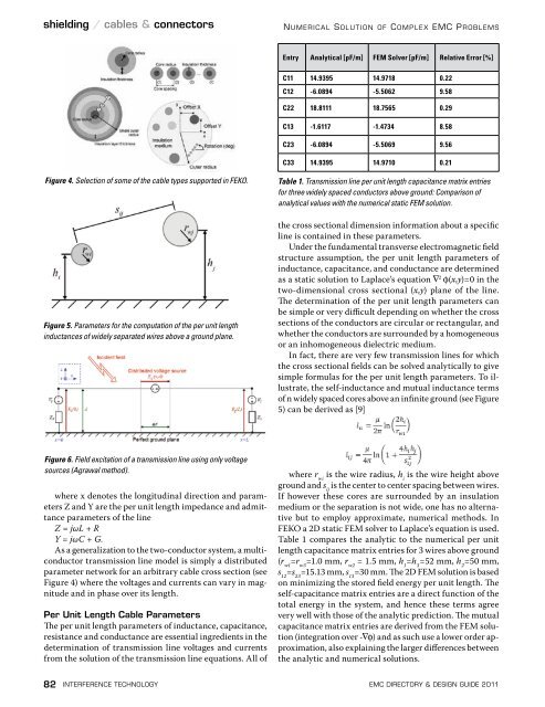
Entry Analytical [pF/m] FEM Solver [pF/m] Relative Error [%]<br />
C11 14.9395 14.9718 0.22<br />
C12 -6.0894 -5.5062 9.58<br />
C22 18.8111 18.7565 0.29<br />
C13 -1.6117 -1.4734 8.58<br />
C23 -6.0894 -5.5069 9.56<br />
C33 14.9395 14.9710 0.21<br />
Figure 4. Selection of some of the cable types supported in FEKO.<br />
Figure 5. Parameters for the computation of the per unit length<br />
inductances of widely separated wires above a ground plane.<br />
Table 1. Transmission line per unit length capacitance matrix entries<br />
for three widely spaced conductors above ground: Comparison of<br />
analytical values with the numerical static FEM solution.<br />
the cross sectional dimension information about a specific<br />
line is contained in these parameters.<br />
Under the fundamental transverse electromagnetic field<br />
structure assumption, the per unit length parameters of<br />
inductance, capacitance, and conductance are determined<br />
as a static solution to Laplace’s equation 2 (x,y)=0 in the<br />
two-dimensional cross sectional (x,y) plane of the line.<br />
The determination of the per unit length parameters can<br />
be simple or very difficult depending on whether the cross<br />
sections of the conductors are circular or rectangular, and<br />
whether the conductors are surrounded by a homogeneous<br />
or an inhomogeneous dielectric medium.<br />
In fact, there are very few transmission lines for which<br />
the cross sectional fields can be solved analytically to give<br />
simple formulas for the per unit length parameters. To illustrate,<br />
the self-inductance and mutual inductance terms<br />
of n widely spaced cores above an infinite ground (see Figure<br />
5) can be derived as [9]<br />
Figure 6. Field excitation of a transmission line using only voltage<br />
sources (Agrawal method).<br />
where x denotes the longitudinal direction and parameters<br />
Z and Y are the per unit length impedance and admittance<br />
parameters of the line<br />
Z = jωL + R<br />
Y = jωC + G.<br />
As a generalization to the two-conductor system, a multiconductor<br />
transmission line model is simply a distributed<br />
parameter network for an arbitrary cable cross section (see<br />
Figure 4) where the voltages and currents can vary in magnitude<br />
and in phase over its length.<br />
Per Unit Length Cable Parameters<br />
The per unit length parameters of inductance, capacitance,<br />
resistance and conductance are essential ingredients in the<br />
determination of transmission line voltages and currents<br />
from the solution of the transmission line equations. All of<br />
where r wi<br />
is the wire radius, h i<br />
is the wire height above<br />
ground and s ij<br />
is the center to center spacing between wires.<br />
If however these cores are surrounded by an insulation<br />
medium or the separation is not wide, one has no alternative<br />
but to employ approximate, numerical methods. In<br />
FEKO a 2D static FEM solver to Laplace’s equation is used.<br />
Table 1 compares the analytic to the numerical per unit<br />
length capacitance matrix entries for 3 wires above ground<br />
(r w1<br />
=r w3<br />
=1.0 mm, r w2<br />
= 1.5 mm, h 1<br />
=h 3<br />
=52 mm, h 2<br />
=50 mm,<br />
s 12<br />
=s 23<br />
=15.13 mm, s 13<br />
=30 mm. The 2D FEM solution is based<br />
on minimizing the stored field energy per unit length. The<br />
self-capacitance matrix entries are a direct function of the<br />
total energy in the system, and hence these terms agree<br />
very well with those of the analytic prediction. The mutual<br />
capacitance matrix entries are derived from the FEM solution<br />
(integration over -) and as such use a lower order approximation,<br />
also explaining the larger differences between<br />
the analytic and numerical solutions.<br />
82 interference technology emc <strong>Directory</strong> & design guide <strong>2011</strong>


![[ thursday ] morning sessions 8:30 am-noon - Interference Technology](https://img.yumpu.com/23176841/1/190x247/-thursday-morning-sessions-830-am-noon-interference-technology.jpg?quality=85)

