

2011 EMC Directory & Design Guide - Interference Technology
2011 EMC Directory & Design Guide - Interference Technology
2011 EMC Directory & Design Guide - Interference Technology

Create successful ePaper yourself
Turn your PDF publications into a flip-book with our unique Google optimized e-Paper software.
filters<br />
M e a s ur e m e n t s a b o v e 1 GHz in Time-Domain<br />
<br />
<br />
<br />
<br />
<br />
<br />
<br />
<br />
<br />
<br />
<br />
<br />
Figure 1. Heterodyne EMI receiver.<br />
<br />
<br />
<br />
<br />
<br />
<br />
<br />
<br />
<br />
<br />
<br />
<br />
<br />
<br />
<br />
<br />
<br />
<br />
<br />
<br />
<br />
<br />
<br />
<br />
<br />
<br />
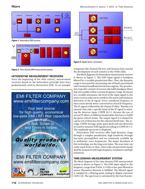
Figure 3. Digital down-conversion.<br />
<br />
<br />
Figure 2. Time-domain EMI measurement system.<br />
HETERODYNE MEASUREMENT RECEIVERS<br />
Since the beginning of the 20th century, measurement<br />
receivers based on the heterodyne principle have been<br />
predominantly used to characterize EMI. As an example,<br />
companies like General Electric and Siemens have started<br />
the development of such systems in the 1920s [5][6].<br />
The block diagram of a heterodyne measurement receiver<br />
is shown in Figure 1. The EMI input signal is bandpass<br />
filtered by a variable preselection filter. Thus, the dynamic<br />
range is increased by attenuating out-of-band narrowband<br />
and transient broadband interference signals. The preselection<br />
typically consists of several selectable bandpass filters<br />
that are tunable within a certain frequency range. By means<br />
of a variable attenuator, the level of the input signal to the<br />
mixer is set in order not to overdrive the mixer and minimize<br />
distortion of the IF-signal. Every considered frequency is<br />
then consecutively down-converted to a fixed IF frequency.<br />
The IF-signal is filtered by the chosen IF-filter. Thereby it is<br />
assured, that only a specific band of the IF signal is reaching<br />
the detector input. CISPR 16-1-1 dictates the use of<br />
several IF-filters of different bandwidths that have to fulfill<br />
the given critical masks. The output signal is evaluated by<br />
a given set of detectors for the selected dwell-time. The average,<br />
CISPR-Average, peak, quasi-peak and rms detectors<br />
are used to measure EMI signals according to CISPR 16-1-1.<br />
The amplitude spectrum is displayed.<br />
Heterodyne EMI receivers offer high dynamic range<br />
through a complex preselection, high sensitivity through<br />
low-noise preamplifiers and are commonly available up<br />
to millimeter wave frequencies. The major drawback of<br />
this technology are the long scan times. The scan time can<br />
easily reach hours or days, when wide measurement bands<br />
shall be measured with high frequency resolution and high<br />
sensitivity.<br />
TIME-DOMAIN MEASUREMENT SYSTEM<br />
The block diagram of the time-domain EMI measurement<br />
system is shown in Figure 2. The EMI input signal in the<br />
frequency range from 9 kHz-1.1 GHz is low-pass filtered to<br />
ensure Shannon’s theorem is fulfilled. The filtered signal<br />
is sampled by a floating-point analog-to-digital converter<br />
(ADC) [2]. The spectrum is calculated by the Fast-Fourier-<br />
116 interference technology emc <strong>Directory</strong> & design guide <strong>2011</strong>


![[ thursday ] morning sessions 8:30 am-noon - Interference Technology](https://img.yumpu.com/23176841/1/190x247/-thursday-morning-sessions-830-am-noon-interference-technology.jpg?quality=85)

