

2011 EMC Directory & Design Guide - Interference Technology
2011 EMC Directory & Design Guide - Interference Technology
2011 EMC Directory & Design Guide - Interference Technology

Create successful ePaper yourself
Turn your PDF publications into a flip-book with our unique Google optimized e-Paper software.
testing & test equipment<br />
N e w <strong>EMC</strong> Requir e m e n t s F o r C o mm e r c i a l Av i o nic s<br />
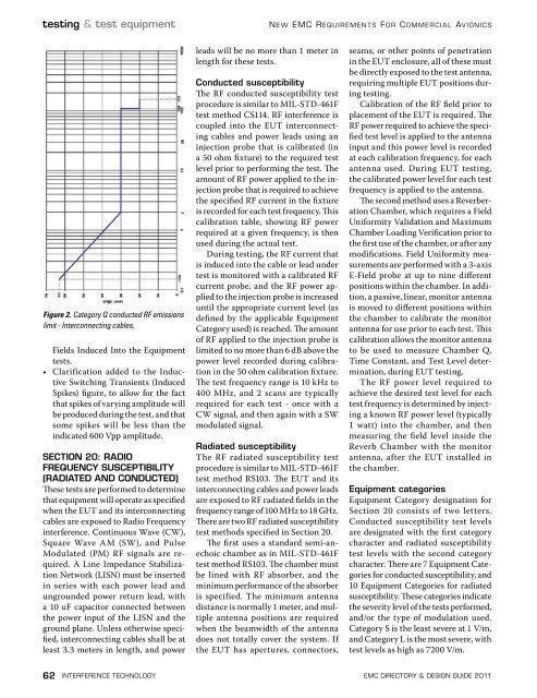
Figure 2. Category Q conducted RF emissions<br />
limit - Interconnecting cables.<br />
Fields Induced Into the Equipment<br />
tests.<br />
• Clarification added to the Inductive<br />
Switching Transients (Induced<br />
Spikes) figure, to allow for the fact<br />
that spikes of varying amplitude will<br />
be produced during the test, and that<br />
some spikes will be less than the<br />
indicated 600 Vpp amplitude.<br />
SECTION 20: RADIO<br />
FREQUENCY SUSCEPTIBILITY<br />
(RADIATED AND CONDUCTED)<br />
These tests are performed to determine<br />
that equipment will operate as specified<br />
when the EUT and its interconnecting<br />
cables are exposed to Radio Frequency<br />
interference. Continuous Wave (CW),<br />
Square Wave AM (SW), and Pulse<br />
Modulated (PM) RF signals are required.<br />
A Line Impedance Stabilization<br />
Network (LISN) must be inserted<br />
in series with each power lead and<br />
ungrounded power return lead, with<br />
a 10 uF capacitor connected between<br />
the power input of the LISN and the<br />
ground plane. Unless otherwise specified,<br />
interconnecting cables shall be at<br />
least 3.3 meters in length, and power<br />
leads will be no more than 1 meter in<br />
length for these tests.<br />
Conducted susceptibility<br />
The RF conducted susceptibility test<br />
procedure is similar to MIL-STD-461F<br />
test method CS114. RF interference is<br />
coupled into the EUT interconnecting<br />
cables and power leads using an<br />
injection probe that is calibrated (in<br />
a 50 ohm fixture) to the required test<br />
level prior to performing the test. The<br />
amount of RF power applied to the injection<br />
probe that is required to achieve<br />
the specified RF current in the fixture<br />
is recorded for each test frequency. This<br />
calibration table, showing RF power<br />
required at a given frequency, is then<br />
used during the actual test.<br />
During testing, the RF current that<br />
is induced into the cable or lead under<br />
test is monitored with a calibrated RF<br />
current probe, and the RF power applied<br />
to the injection probe is increased<br />
until the appropriate current level (as<br />
defined by the applicable Equipment<br />
Category used) is reached. The amount<br />
of RF applied to the injection probe is<br />
limited to no more than 6 dB above the<br />
power level recorded during calibration<br />
in the 50 ohm calibration fixture.<br />
The test frequency range is 10 kHz to<br />
400 MHz, and 2 scans are typically<br />
required for each test - once with a<br />
CW signal, and then again with a SW<br />
modulated signal.<br />
Radiated susceptibility<br />
The RF radiated susceptibility test<br />
procedure is similar to MIL-STD-461F<br />
test method RS103. The EUT and its<br />
interconnecting cables and power leads<br />
are exposed to RF radiated fields in the<br />
frequency range of 100 MHz to 18 GHz.<br />
There are two RF radiated susceptibility<br />
test methods specified in Section 20.<br />
The first uses a standard semi-anechoic<br />
chamber as in MIL-STD-461F<br />
test method RS103. The chamber must<br />
be lined with RF absorber, and the<br />
minimum performance of the absorber<br />
is specified. The minimum antenna<br />
distance is normally 1 meter, and multiple<br />
antenna positions are required<br />
when the beamwidth of the antenna<br />
does not totally cover the system. If<br />
the EUT has apertures, connectors,<br />
seams, or other points of penetration<br />
in the EUT enclosure, all of these must<br />
be directly exposed to the test antenna,<br />
requiring multiple EUT positions during<br />
testing.<br />
Calibration of the RF field prior to<br />
placement of the EUT is required. The<br />
RF power required to achieve the specified<br />
test level is applied to the antenna<br />
input and this power level is recorded<br />
at each calibration frequency, for each<br />
antenna used. During EUT testing,<br />
the calibrated power level for each test<br />
frequency is applied to the antenna.<br />
The second method uses a Reverberation<br />
Chamber, which requires a Field<br />
Uniformity Validation and Maximum<br />
Chamber Loading Verification prior to<br />
the first use of the chamber, or after any<br />
modifications. Field Uniformity measurements<br />
are performed with a 3-axis<br />
E-Field probe at up to nine different<br />
positions within the chamber. In addition,<br />
a passive, linear, monitor antenna<br />
is moved to different positions within<br />
the chamber to calibrate the monitor<br />
antenna for use prior to each test. This<br />
calibration allows the monitor antenna<br />
to be used to measure Chamber Q,<br />
Time Constant, and Test Level determination,<br />
during EUT testing.<br />
The RF power level required to<br />
achieve the desired test level for each<br />
test frequency is determined by injecting<br />
a known RF power level (typically<br />
1 watt) into the chamber, and then<br />
measuring the field level inside the<br />
Reverb Chamber with the monitor<br />
antenna, after the EUT installed in<br />
the chamber.<br />
Equipment categories<br />
Equipment Category designation for<br />
Section 20 consists of two letters.<br />
Conducted susceptibility test levels<br />
are designated with the first category<br />
character and radiated susceptibility<br />
test levels with the second category<br />
character. There are 7 Equipment Categories<br />
for conducted susceptibility, and<br />
10 Equipment Categories for radiated<br />
susceptibility. These categories indicate<br />
the severity level of the tests performed,<br />
and/or the type of modulation used.<br />
Category S is the least severe at 1 V/m,<br />
and Category L is the most severe, with<br />
test levels as high as 7200 V/m.<br />
62 interference technology emc <strong>Directory</strong> & design guide <strong>2011</strong>


![[ thursday ] morning sessions 8:30 am-noon - Interference Technology](https://img.yumpu.com/23176841/1/190x247/-thursday-morning-sessions-830-am-noon-interference-technology.jpg?quality=85)

