

2011 EMC Directory & Design Guide - Interference Technology
2011 EMC Directory & Design Guide - Interference Technology
2011 EMC Directory & Design Guide - Interference Technology

You also want an ePaper? Increase the reach of your titles
YUMPU automatically turns print PDFs into web optimized ePapers that Google loves.
shielding / cables & connectors<br />
Figure 13. FEKO model for an L-shaped single conductor cable over a<br />
ground shape.<br />
shield) and interior (cable bundle) problems only couple<br />
weakly through the transfer impedance. A very similar<br />
approach has been proposed in [17].<br />
The steps of the irradiating case of the analysis method<br />
are shown in Figure 10 and are as follows:<br />
1. Set up the problem geometry and cable analysis request.<br />
The metallic structure will be meshed with triangular<br />
elements. The exterior of the cable path will be included<br />
Num e ric a l S o l u t i o n of C o mpl e x <strong>EMC</strong> Probl e m s<br />
in the full-wave analysis with the MoM using thin shell<br />
wire segment elements of which the radius, thickness<br />
and material properties are the same as that of the shield.<br />
2. Solve the external MoM system to obtain the shield (wire<br />
segment) exterior current. The MoM solution yields the<br />
total current flowing on the shield exterior.<br />
3. Use the transfer impedance of the shield to convert the<br />
exterior shield current to a distributed voltage source<br />
exciting the multi-conductor transmission line interior<br />
problem.<br />
4. Solve the internal problem using multi-conductor transmission<br />
line circuit analysis.<br />
In a similar manner also the radiating case can be dealt<br />
with.<br />
VALIDATION AND APPLICATION EXAMPLES<br />
Although the techniques presented in this paper can be<br />
applied to complex real-world problems (e.g. cable harness<br />
running in a car), we present in the following rather simple<br />
validation and application examples. These examples have<br />
the advantage that full wave MoM solutions (i.e. discretizing<br />
the cable into MoM wire segments) exist as reference<br />
to compare to the combined MoM/MTL technique, or<br />
measurements / reference results from literature based on<br />
other techniques or other implementations available.<br />
RG58 Coaxial Cable Close to Monopole Antenna<br />
(Irradiation)<br />
A monopole antenna of 10 m height is fed by an input power<br />
of 10 W and is radiating in the neighborhood of an RG58<br />
coaxial cable which forms a U-shaped loop of length 24.24<br />
m. The axis of the cable is assumed to be 10 mm above a PEC<br />
ground with both shield ends short-circuited to ground.<br />
The coaxial core is terminated in 50 Ω to the shield and<br />
the shield transfer impedance is available from a measurement<br />
database. The frequency range extends from 1 MHz<br />
to 35 MHz. Figure 11 shows the configuration setup while<br />
Figure 12 compares the FEKO solution to reference results<br />
[18] for the voltage at the cable end closest to the antenna<br />
(Port 1). The results from [18] are based on a standard MTL<br />
/ MoM combination which is only applicable to cables<br />
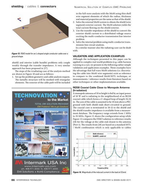
Figure 14. Magnitude of the induced current in the load at CCend.<br />
86 interference technology emc <strong>Directory</strong> & design guide <strong>2011</strong>


![[ thursday ] morning sessions 8:30 am-noon - Interference Technology](https://img.yumpu.com/23176841/1/190x247/-thursday-morning-sessions-830-am-noon-interference-technology.jpg?quality=85)

