

2011 EMC Directory & Design Guide - Interference Technology
2011 EMC Directory & Design Guide - Interference Technology
2011 EMC Directory & Design Guide - Interference Technology

You also want an ePaper? Increase the reach of your titles
YUMPU automatically turns print PDFs into web optimized ePapers that Google loves.
H o f f m a nn, Br aun, Frech, Rus s e r<br />
filters<br />
<br />
<br />
<br />
<br />
<br />
<br />
<br />
<br />
<br />
<br />
<br />
<br />
<br />
<br />
<br />
<br />
<br />
<br />
<br />
<br />
<br />
<br />
Figure 6. 1.1 - 6 GHz down-converter.<br />
broadband subbands are consecutively down-converted<br />
to the 1.1-6 GHz band via broadband, low-conversion loss<br />
mixer and fed to the input of the 1.1 - 6 GHz down-converter.<br />
HARDWARE IMPLEMENTATION<br />
As most of the EMI in the frequency range above 1 GHz, e.g.<br />
higher harmonics of communication systems, is low-level in<br />
nature, high sensitivity is mandatory for frequencies above 1<br />
GHz. Increased attenuation of cable assemblies above 1 GHz<br />
in common test environments aggravates the problem. A low<br />
noise figure of the input stage is critical for high sensitivity.<br />
This correlates with a low attenuation of the first stages of<br />
the multi-stage broadband down-converter, as (5) for the<br />
calculation of the noise figure F of a cascaded system with<br />
N stages [10] implies<br />
F = 1 + F 1 + F 2 − 1<br />
+ F 3 − 1<br />
+ ... + F N − 1<br />
,<br />
G 1 G 1 G N−1<br />
2 ∏<br />
G k<br />
k=1<br />
(5)<br />
where G i<br />
is the available power gain of stage i and F i<br />
is<br />
the noise figure of stage i.<br />
In the presented measurement system, high-gain, lownoise<br />
InGaP/GaAs MMIC preamplifiers yield a system<br />
noise figure of around 6-8 dB, rendering the use of external<br />
amplifiers unnecessary. To further increase the system’s<br />
sensitivity and dynamic range, low-noise double balanced<br />
mixers with low conversion loss and high 1 dB compression<br />
point are used.<br />
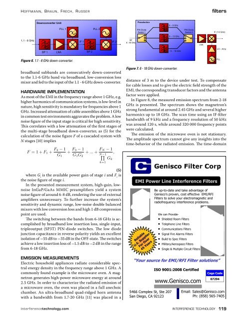
The switching between the bands from 6-18 GHz is accomplished<br />
by broadband low insertion loss, single-input,<br />
tripleoutput (SP3T) PIN-diode switches. The low diode<br />
junction capacitance in reverse polarity yields an excellent<br />
isolation of -55 dB to -35 dB in the OFF-state. The switches<br />
achieve a low insertion loss of -1.5 dB to -2 dB in the range<br />
from 6-18 GHz.<br />
EMISSION MEASUREMENTS<br />
Electric household appliances radiate considerable spectral<br />
energy density in the frequency range above 1 GHz. A<br />
commonly found example is the microwave oven. A magnetron<br />
generates high-power microwave energy at around<br />
2.5 GHz. In order to characterize the radiated emission of<br />
a microwave oven, the oven was placed in a full anechoic<br />
chamber. An ultra-broadband quad-ridged horn antenna<br />
with a bandwidth from 1.7-20 GHz [11] was placed in a<br />
Figure 7. 6 - 18 GHz down-converter.<br />
distance of 3 m to the device under test. To compensate<br />
for cable losses and to give the electric field strength of the<br />
EMI, the corresponding transducer factors and the antenna<br />
factor were applied.<br />
In Figure 8, the measured emission spectrum from 2-18<br />
GHz is presented. The spectrum shows the magnetron’s<br />
strong fundamental at around 2.45 GHz and several higher<br />
harmonics up to 18 GHz. The scan time using an IF-filter<br />
bandwidth of 9 kHz and a frequency resolution of 50 kHz<br />
was around 120 s, while around 320 000 frequency points<br />
were calculated.<br />
The emission of the microwave oven is not stationary.<br />
The amplitude spectrum cannot give any insights into the<br />
time-behavior of the radiated emission. The time-domain<br />
EMI Power Line <strong>Interference</strong> Filters<br />
Reliable<br />
U.S. Supplier<br />
For Over<br />
45 Years<br />
“Your source for EMI/RFI Filter solutions”<br />
5466 Complex St, Ste 207<br />
San Diego, CA 92123<br />
Be up-to-date and take advantage of<br />
Genisco’s proven, cost effective EMI/RFI<br />
Filters to solve your electromagnetic and<br />
radiofrequency interference problems.<br />
We can Provide-<br />
• Shielded Room Filters<br />
• Telephone Line Filters<br />
• Communications Filters<br />
• Signal Fire Alarms Filters<br />
• Build to Spec Filters<br />
• Military/Aerospace Filters<br />
• Single & Multiple Circuit Filters<br />
ISO 9001:2008 Certified<br />
www.Genisco.com<br />
<br />
Cage Code<br />
07294<br />
Email: Sales@Genisco.com<br />
Ph: (858) 565-7405<br />
interferencetechnology.com interference technology 119


![[ thursday ] morning sessions 8:30 am-noon - Interference Technology](https://img.yumpu.com/23176841/1/190x247/-thursday-morning-sessions-830-am-noon-interference-technology.jpg?quality=85)

