Jahresbericht 2005 - IPHT Jena
Jahresbericht 2005 - IPHT Jena
Jahresbericht 2005 - IPHT Jena

You also want an ePaper? Increase the reach of your titles
YUMPU automatically turns print PDFs into web optimized ePapers that Google loves.
OPTIK / OPTICS<br />
Coating material NA Layer Cut-back method: OTDR:<br />
(coated thickness Loss [dB/km] Loss [dB/km]<br />
silica fibre) [µm]<br />
800nm 1310nm 1550nm 850nm 1310nm 1550nm<br />
Silicone RT601 0.358 50 20 25 250 13 29 n.m.<br />
Ormogel HG-Li-V-T 0.410 5 25 51 150 23 37 (70)<br />
1D3-63 (Acrylate) 0.404 50 34 59 180 (50) 75 n.m.<br />
Luv PC 373 (Acrylate) 0.447–0.127 50 9 17 60 5 16 45<br />
Teflon AF 0.606 5–10 9 7 8 4 5 6<br />
Tab. 2.1: Loss in silica fibres with different coating materials, measured by the cut-back method and by<br />
OTDR (n.m. = not measurable, because of limited dynamic range of OTDR; cut-back method works without<br />
limitation of measurable loss).<br />
2 With the Optical Time Domain Analysis<br />
(OTDR), the loss can be evaluated with a spatial<br />
resolution of some meters, but only at<br />
selected wavelengths. Fibre lengths >60 m<br />
can be analysed; the measurements should be<br />
executed from both fibre ends. One of the<br />
available devices applies a wavelength of<br />
850nm and illuminates the fibre under test with<br />
NA 0.20 (spot size 50 µm); another device for<br />
1310 nm and 1550 nm implements NA 0.10<br />
(spot size 10 µm).<br />
Both methods supplement each other and are<br />
suitable especially for the comparison of losses<br />
in fibres with different coatings, but equal fibre<br />
diameters.<br />
The results obtained with both methods are compared<br />
in Tab. 2.1 (the wavelengths are determined<br />
by the OTDR devices) and indicate a sufficient<br />
consistency.<br />
The low loss and the high NA achieved with the<br />
Teflon AF coating, as well as the absence of<br />
additional absorption bands (apart from OH<br />
absorption) are particularly advantageous for<br />
cladding pumping. But the Teflon layer that can<br />
be implemented is too thin for many applications.<br />
The low-index Acrylate Luv 370–444, but also Silicone<br />
RT601 provide a moderate pump loss and<br />
an adequate layer thickness. However, characteristic<br />
absorption bands may be detrimental, e.g.<br />
the Silicone absorption around the common<br />
pump wavelength of 915 nm.<br />
Besides the effects on fibre loss, the coating<br />
materials differ in their mechanical and thermal<br />
properties, which should also be taken into<br />
account in high pump power applications.<br />
2.2.6 Studies of the mode behaviour<br />
of multi-core fibre structures<br />
(K. Mörl, J. Kobelke, K. Schuster)<br />
There are various reasons to build-up the active<br />
cores of microstructured fibres from single doped<br />
filaments. One of them is to achieve a mode field<br />
as large as possible. The preparation is carried<br />
out usually by repeated packaging and stretching<br />
of rare-earth-doped elements made by the well<br />
established MCVD technique, soaking in rareearth<br />
solutions and subsequent drawing of the<br />
microstructured fibre by means of the “stack and<br />
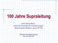
draw“ technique. Fig. 2.7 shows the central part<br />
of a PCF with 7 × 7 active Yb-doped filaments.<br />
Fig. 2.7: Central part of a PCF with 7 × 7 active<br />
doped filaments .<br />
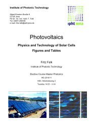
A matter of particular interest is the mode behaviour<br />
of such structures, especially the optical coupling<br />
of the single elements (formation of a<br />
“super-mode”). Fig. 2.8 shows the changing<br />
mode picture at the end of a short piece of the<br />
fibre shown in Fig. 2.7, achieved by launching<br />
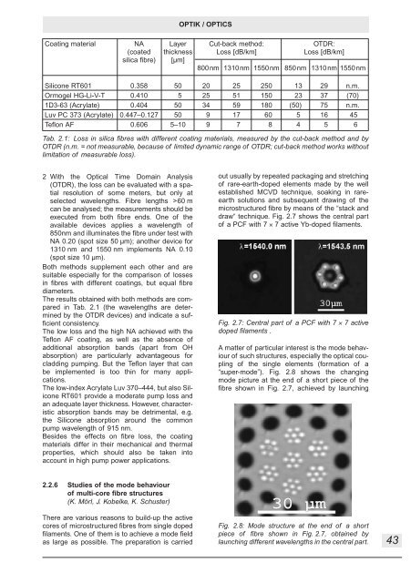
Fig. 2.8: Mode structure at the end of a short<br />
piece of fibre shown in Fig. 2.7, obtained by<br />
launching different wavelengths in the central part.<br />
43