Smalltalk and Object Orientation: an Introduction - Free
Smalltalk and Object Orientation: an Introduction - Free
Smalltalk and Object Orientation: an Introduction - Free

Create successful ePaper yourself
Turn your PDF publications into a flip-book with our unique Google optimized e-Paper software.
Deployment diagrams . Deployment diagrams (previously known as platform diagrams). As this<br />
model attempts to capture the topology of the system once it is deployed, it reflects the physical<br />
topology upon which the software system is to execute.<br />
17.3 Use case diagrams<br />
Use case diagrams explain how a system (or subsystem) will be used. The elements which interac t with<br />
the system c<strong>an</strong> be hum<strong>an</strong>s, other computers or dumb devices which process or produce data. The<br />
diagrams thus present a collection of use cases which illustrate what the system is expected to do, in<br />
terms of its external services or interfaces. Such di agrams are very import<strong>an</strong>t for illustrating overall<br />
system functionality (to both technical <strong><strong>an</strong>d</strong> non -technical personnel). In addition they c<strong>an</strong> act as the<br />
context within which the rest of the system is defined.<br />
Case based retrieval system<br />
Load casebase<br />
<br />
Telephonist<br />
<br />
Service<br />
Engineer<br />
Delete case<br />
Save casebase<br />
Search<br />
casebase<br />
Add case<br />
Printout case<br />
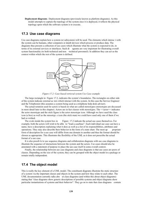
Figure 17.2: Case-based retrieval system Use Case example<br />
The large rect<strong>an</strong>gle in Figure 17.2, indicates the system’s boundaries. The rect<strong>an</strong>gles on either side<br />
of the system indicate external ac tors which interact with the system. In this case the Service Engineer<br />
<strong><strong>an</strong>d</strong> the Telephonist (this assumes a system being used as a telephone help desk adviser).<br />
The actual notation used for actors is based on what are called stereotypes (stereotypes are discussed<br />
in more detail later in this chapter). Actors are in fact classes with stereotypes. The indicates<br />
the actor stereotype <strong><strong>an</strong>d</strong> the stick figure is the actor stereotype icon. Although we have used the class<br />
icon (a box) as well as the stereotyp e icon (the stick m<strong>an</strong>) we could have used only one of them if we<br />
had so wished.<br />
The ovals inside the system box in Figure 17.2 indicate the actual use cases themselves. For<br />
example, both the actors will wish to be able to “load a casebase”. Each individual use case c<strong>an</strong> have a<br />
name, have a description explaining what it does as well as a list of its responsibilities, attributes <strong><strong>an</strong>d</strong><br />
operations. They may also describe their behavior in the form of a state chart. The most ap propriate<br />
form of description for a use case will differ from one domain to <strong>an</strong>other <strong><strong>an</strong>d</strong> thus the format should be<br />
chosen as appropriate. This illustrates the flexibility of the UML as it does not prescribe the actual<br />
format of a use case.<br />
It is also possib le to use sequence diagrams <strong><strong>an</strong>d</strong> collaboration diagrams with use case diagrams to<br />
illustrate the sequence of interactions between the system <strong><strong>an</strong>d</strong> the actors. Use cases should also be<br />
<strong>an</strong>notated with a statement of purpose to place the use case itself in some overall context.<br />
Finally, the relationship between use case diagrams <strong><strong>an</strong>d</strong> class diagrams is that use cases are peers of<br />
classes. Depending on the size of the system, they c<strong>an</strong> be grouped with the object model in a package or<br />
remain totally independent.<br />
17.4 The object model<br />
This is really the key element of a UML model. The constituent diagrams illustrate the static structure<br />
of a system via the import<strong>an</strong>t classes <strong><strong>an</strong>d</strong> objects in the system <strong><strong>an</strong>d</strong> how they relate to each other. The<br />
UML documentation currently talks abo ut class diagrams (<strong><strong>an</strong>d</strong> within this about object diagrams)<br />
stating that “class diagrams show generic descriptions of possible systems <strong><strong>an</strong>d</strong> object diagrams show<br />
particular inst<strong>an</strong>tiations of systems <strong><strong>an</strong>d</strong> their behavior”. They go on to state that class diagrams contain<br />
139