Smalltalk and Object Orientation: an Introduction - Free
Smalltalk and Object Orientation: an Introduction - Free
Smalltalk and Object Orientation: an Introduction - Free

Create successful ePaper yourself
Turn your PDF publications into a flip-book with our unique Google optimized e-Paper software.
DrawingView<br />
model<br />
SmallDraw<br />
drawingView<br />
drawingModel<br />
controller<br />
defaultController<br />
DrawingController<br />
view<br />
model<br />
DrawingModel<br />
style<br />
nodes<br />
<strong>an</strong>OrderedCollection<br />
BoxWidget<br />
origin<br />
extent<br />
border<br />
CircleWidget<br />
origin<br />
extent<br />
border<br />
LineWidget<br />
origin<br />
extent<br />
border<br />
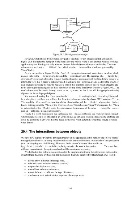
Figure 29.5: The object relationships<br />
However, what inherits from what is only part of the story for <strong>an</strong>y object oriented application.<br />
Figure 29.5 illustrates the next part of the story: how the objects relate to one <strong>an</strong>other within a working<br />
application (note this diagram only presents the user defined objects within the application. There are<br />
other objects such as the UIBuilder which are also involved but which are generated by<br />
VisualWorks).<br />
As you c<strong>an</strong> see from Figure 29.5 the SmallDraw application model has inst<strong>an</strong>ce variables which<br />
possess links to the drawingModel <strong><strong>an</strong>d</strong> the drawingView. The presence of a link to the<br />
drawingView object allows the window building facilities associated with the SmallDraw window to<br />
inform the view that it needs to redisplay itself. The link to the drawingModel allows the effects of<br />
user interaction outside the view to be passe d onto it. For example, the user selects which object to add<br />
to the drawing by selecting one of three buttons at the top of the SmallDraw window ( Figure 29.1). The<br />
user’s choice must be passed through to the drawingModel so that it c<strong>an</strong> add the appropriate drawing<br />
object to its list of displayed objects.<br />
It is also worth noting that if you examine the<br />
DrawingModel, DrawingView <strong><strong>an</strong>d</strong><br />
DrawingController you will see that these three classes exhibit the classic MVC structure. T he<br />
View <strong><strong>an</strong>d</strong> the Controller have knowledge of each other <strong><strong>an</strong>d</strong> the Model, whereas the Model<br />
knows nothing about the View or the Controller. This is because VisualWorks records the View<br />
as a dependent of the Model when the view records the presence of the mode l (using the super<br />
model: aModel. message expression).<br />
Finally it is worth pointing out that in this case the DrawingModel is a relatively simple model<br />
which merely records a set of nodes in <strong>an</strong> OrderedCollection. These nodes could be <strong>an</strong>ything <strong><strong>an</strong>d</strong><br />
could be displayed in <strong>an</strong>y way. It is the nodes themselves which determine what they should look like<br />
when drawn.<br />
29.4 The interactions between objects<br />
We have now examined what the physical structure of the application is but not how the objects within<br />
that application interact. In m<strong>an</strong>y situations this c<strong>an</strong> be extracted from the source code of the application<br />
(with varying degree’s of difficulty). However, in the case of a custom view within <strong>an</strong><br />
ApplicationModel, it is useful to explicitly describe the system interaction. There are four<br />
different interactions in the system <strong><strong>an</strong>d</strong> each will be considered separately.<br />
We shall adopt the following conventions for the diagrams illustrating the interactions between the<br />
objects (these diagrams are based on the mech<strong>an</strong>ism diagrams described by [Rumbaugh et al 1991]):<br />
• a solid arrow indicates a message send,<br />
• a dashed arrow indicates inst<strong>an</strong>ce creation,<br />
• a square box indicates a class,<br />
• a round box indicates <strong>an</strong> inst<strong>an</strong>ce,<br />
• a name in brackets indicates the type of inst<strong>an</strong>ce,<br />
• numbers are used to indicate the sequence of message sends.<br />
247