Smalltalk and Object Orientation: an Introduction - Free
Smalltalk and Object Orientation: an Introduction - Free
Smalltalk and Object Orientation: an Introduction - Free

You also want an ePaper? Increase the reach of your titles
YUMPU automatically turns print PDFs into web optimized ePapers that Google loves.
• A conditional indicator. This is a question mark (?), optionally followed by a Boole<strong>an</strong><br />
expression in parentheses. The iteration <strong><strong>an</strong>d</strong> conditional indicators are mutually exclusive.<br />
3. A return value name followed by <strong>an</strong> assignment sign (“:=“). If present this indicates that the<br />
procedure returns a value designated by the given name. The use of the same name elsewhere in<br />
the diagram designates the exact same value. If no return value is specified, then the procedure<br />
operates by side effects.<br />
4. The name of the message . This is <strong>an</strong> event name or operation name. It is unnecessary to specify<br />
the class of <strong>an</strong> operation since this is implicit in the target object.<br />
5. The argument list of the message . The arguments are expressions defined in terms of input<br />
values of the nesting procedure, local return values of other procedures <strong><strong>an</strong>d</strong> attribute values of<br />
the object sending the message.<br />
Argument values <strong><strong>an</strong>d</strong> return values for messages may optionally be shown graphically using small<br />
data flow tokens near a message. Each token is a small circle, with <strong>an</strong> arrow showing the direction of<br />
the data flow, labeled with the name of the argument or result.<br />
18.2.3 State machine diagrams<br />
Scenarios are used to help underst<strong><strong>an</strong>d</strong> how the objects within the system collaborate, where as state<br />
diagrams illustrates how these objects behave internally. That is, state diagrams relate events to state<br />
tr<strong>an</strong>sitions <strong><strong>an</strong>d</strong> states. The tr<strong>an</strong>sitions ch<strong>an</strong>ge the state of the system <strong><strong>an</strong>d</strong> are triggered by events. The<br />
notation used to document state diagrams is based on that developed by Harel [Harel et al 1987, Harel<br />
1988] <strong><strong>an</strong>d</strong> termed Statecharts.<br />
Statecharts are a vari <strong>an</strong>t of the finite -state machine formalism which reduces the apparent<br />
complexity of a graphical representation of a finite -state machine. This is accomplished through the<br />
addition of a simple graphical representation of certain common patterns of finite sta te machine usage.<br />
As a result, what might be a complex subgraph in a “basic” finite state machine is replaced by a single<br />
graphical construct.<br />
Each state diagram (statecharts are referred to as state diagrams in UML) has a start point a t which<br />
the state is entered <strong><strong>an</strong>d</strong> may have <strong>an</strong> exit or termination point at which the state is terminated. The state<br />
may also contain concurrency as well as synchronization of concurrent activities.<br />
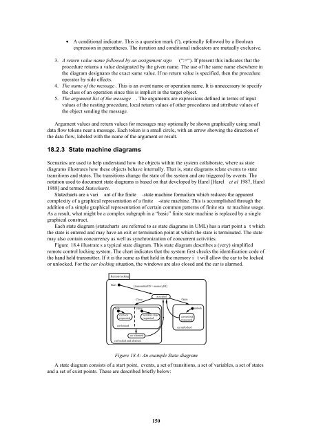
Figure 18.4 illustrate s a typical state diagram. This state diagram describes a (very) simplified<br />
remote control locking system. The chart indicates that the system first checks the identification code of<br />
the h<strong><strong>an</strong>d</strong> held tr<strong>an</strong>smitter. If it is the same as that held in the memory i t will allow the car to be locked<br />
or unlocked. For the car locking situation, the windows are also closed <strong><strong>an</strong>d</strong> the car is alarmed.<br />
Remote locking<br />
Start<br />
[tr<strong>an</strong>smittedID = memoryID]<br />
Close<br />
accepted<br />
Open<br />
lock<br />
close<br />
unlock<br />
car lock<br />
requested<br />
car locked<br />
window close<br />
requested<br />
car unlock<br />
requested<br />
car unlocked<br />
car alarmed<br />
car locked <strong><strong>an</strong>d</strong> alramed<br />
Figure 18.4: An example State diagram<br />
A state diagram consists of a start point, events, a set of tr<strong>an</strong>sitions, a set of variables, a set of states<br />
<strong><strong>an</strong>d</strong> a set of exist points. These are described briefly below:<br />
150