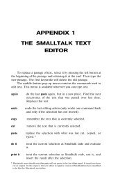
Smalltalk and Object Orientation: an Introduction - Free
Smalltalk and Object Orientation: an Introduction - Free
Smalltalk and Object Orientation: an Introduction - Free

Create successful ePaper yourself
Turn your PDF publications into a flip-book with our unique Google optimized e-Paper software.
• Will the actor have to read/write/ch<strong>an</strong>ge <strong>an</strong>y of the system information?<br />
• Will the actor have to inform the system about outside ch<strong>an</strong>ges?<br />
• Does the actor wish to be informed about unexpected ch<strong>an</strong>ges?<br />
Early in the <strong>an</strong>alysis process it is often enough just to identify the possible uses cases <strong><strong>an</strong>d</strong> not to worry<br />
about their details. Once a reasonable set of uses are identified, it may be possible to <strong>an</strong>alyze the<br />
systems requirements in greater detail in order to flesh out the uses cases. Use case identification tends<br />
to be iterative <strong><strong>an</strong>d</strong> should not be treated as a single step process for all but the simplest of systems.<br />
Having identified the uses cases, we c<strong>an</strong> identify the steps performed within each use case. In m<strong>an</strong>y<br />
cases this c<strong>an</strong> help to identify omissions <strong><strong>an</strong>d</strong> over generalizations in <strong>an</strong>y problem statement or domain<br />
underst<strong><strong>an</strong>d</strong>ing, that we may have.<br />
For the simple b<strong>an</strong>k account system mentioned above, a typical use case might be:<br />
Check account is started by Customer when they w<strong>an</strong>t to find out their current bal<strong>an</strong>ce.<br />
This is accomplished by:<br />
1. typing in their account number followed by the PIN<br />
2. requesting the current bal<strong>an</strong>ce of their account (this may be on screen or on a<br />
print out)<br />
3. receiving the bal<strong>an</strong>ce<br />
4. acknowledging receipt of the bal<strong>an</strong>ce<br />
5. logging off the system<br />
Notice that the first element of the use case is a statement of its purpose. This is then followed by the<br />
sequence of steps performed by the use case. The steps described above are referred to as the basic<br />
course of the use cases. That is, the normal way in which the use case will execute. In general uses<br />
cases only possess a single basic course. However, they may possess one or more alternative courses.<br />
These alternatives deal with exceptional situations or errors. For example, what if the customer does not<br />
have a current account, what happens if they do not accept receipt of their bal<strong>an</strong>ce?<br />
19.3.1.3 Use case models<br />
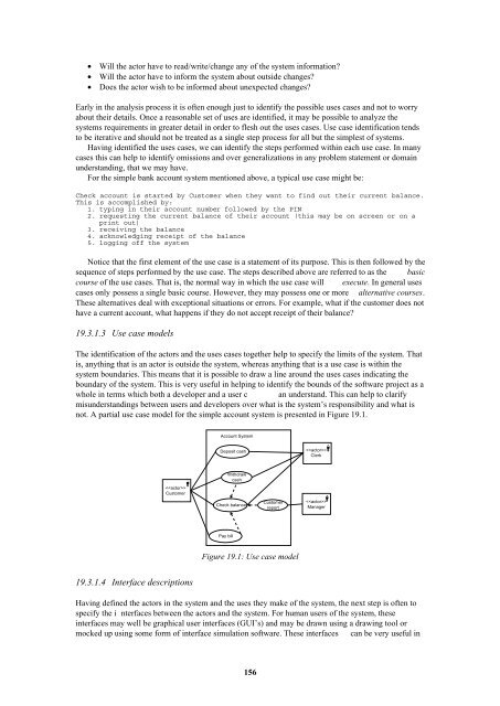
The identification of the actors <strong><strong>an</strong>d</strong> the uses cases together help to specify the limits of the system. That<br />
is, <strong>an</strong>ything that is <strong>an</strong> actor is outside the system, whereas <strong>an</strong>ything that is a use case is within the<br />
system boundaries. This me<strong>an</strong>s that it is possible to draw a line around the uses cases indicating the<br />
boundary of the system. This is very useful in helping to identify the bounds of the software project as a<br />
whole in terms which both a developer <strong><strong>an</strong>d</strong> a user c <strong>an</strong> underst<strong><strong>an</strong>d</strong>. This c<strong>an</strong> help to clarify<br />
misunderst<strong><strong>an</strong>d</strong>ings between users <strong><strong>an</strong>d</strong> developers over what is the system’s responsibility <strong><strong>an</strong>d</strong> what is<br />
not. A partial use case model for the simple account system is presented in Figure 19.1.<br />
Account System<br />
Deposit cash<br />
<br />
Clerk<br />
<br />
Customer<br />
Withdraw<br />
cash<br />
Check bal<strong>an</strong>ce<br />
Customer<br />
report<br />
<br />
M<strong>an</strong>ager<br />
Pay bill<br />
Figure 19.1: Use case model<br />
19.3.1.4 Interface descriptions<br />
Having defined the actors in the system <strong><strong>an</strong>d</strong> the uses they make of the system, the next step is often to<br />
specify the i nterfaces between the actors <strong><strong>an</strong>d</strong> the system. For hum<strong>an</strong> users of the system, these<br />
interfaces may well be graphical user interfaces (GUI’s) <strong><strong>an</strong>d</strong> may be drawn using a drawing tool or<br />
mocked up using some form of interface simulation software. These interfaces c<strong>an</strong> be very useful in<br />
156