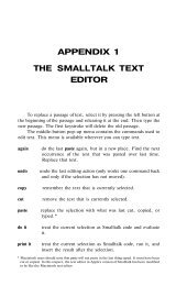
Smalltalk and Object Orientation: an Introduction - Free
Smalltalk and Object Orientation: an Introduction - Free
Smalltalk and Object Orientation: an Introduction - Free

You also want an ePaper? Increase the reach of your titles
YUMPU automatically turns print PDFs into web optimized ePapers that Google loves.
Operations c<strong>an</strong> be of the following types:<br />
• entry (executed when the state is entered). These are the same as specifying <strong>an</strong> operation on a<br />
tr<strong>an</strong>sition. They are useful if all tr<strong>an</strong>sitions into a state perform the same operation (rather th<strong>an</strong><br />
need to specify the same operation on each tr<strong>an</strong>sition). Such operations are considered to be<br />
inst<strong>an</strong>t<strong>an</strong>eous.<br />
• exit (executed when the state is exited). T hese are less common th<strong>an</strong> entry actions <strong><strong>an</strong>d</strong> indicate<br />
<strong>an</strong> operation performed before <strong>an</strong>y tr<strong>an</strong>sition from the state occurs.<br />
• do (executed while the state is active). These are operations which start on entry to the state <strong><strong>an</strong>d</strong><br />
terminate when the state is exited.<br />
• event. A specified event c<strong>an</strong> also trigger off <strong>an</strong> operation while within a particular state. For<br />
example, the event help could trigger the help operation which in the state active.<br />
Each operation is separated from its type by a forward slash (“/”). The ordering of operations is:<br />
operation on incoming tr<strong>an</strong>sitions -> entry operations -> do operations -> exit operations -><br />
operations on outgoing tr<strong>an</strong>sitions.<br />
State diagrams allow a state to be a single state variable, or a set of substates. This allows for<br />
complex hierarchical models to be developed gradually as a series of nested behavior patterns. This<br />
me<strong>an</strong>s that a state c<strong>an</strong> actually be a State diagram in its own right. For example, car alarmed is a single<br />
state, however the car locked state, is actually <strong>an</strong>other State diagram. Notice that the tr<strong>an</strong>sition from car<br />
alarmed to accepted jumps from <strong>an</strong> inner state to <strong>an</strong> outer state.<br />
The dotted line down the middle of car locked state indicates that the two halves of that state run<br />
concurrently. That is, the car is locked as the windows are closed.<br />
A special type of state, called a history state, is used to represent a state which must be remembered<br />
<strong><strong>an</strong>d</strong> used the next time the (outer) state is entered. The symbol for a history state is <strong>an</strong> H in a circle.<br />
18.2.3.6 A set of exit points<br />
Exit points are used to specify the result of the State diagram. They also terminate the execution of<br />
the State diagram.<br />
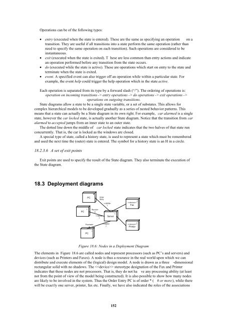
18.3 Deployment diagrams<br />
PC<br />
*<br />
Order<br />
Entry<br />
<br />
<br />
Fax<br />
1<br />
PC<br />
1<br />
Receivin<br />
g<br />
<br />
1<br />
Server<br />
Purchasin<br />
g<br />
<br />
1<br />
<br />
Printer<br />
PC<br />
1<br />
Figure 18.6: Nodes in a Deployment Diagram<br />
The elements in Figure 18.6 are called nodes <strong><strong>an</strong>d</strong> represent processors (such as PC’s <strong><strong>an</strong>d</strong> servers) <strong><strong>an</strong>d</strong><br />
devices (such as Printers <strong><strong>an</strong>d</strong> Faxes). A node is thus a resource in the real world upon which we c<strong>an</strong><br />
distribute <strong><strong>an</strong>d</strong> execute elements of the (logical) design model. A node is drawn as a three -dimensional<br />
rect<strong>an</strong>gular solid with no shadows. The stereotype designation of the Fax <strong><strong>an</strong>d</strong> Printer<br />
indicates that these nodes are not processors. That is, they do not ha ve <strong>an</strong>y processing ability (at least<br />
not from the point of view of the model being constructed). It is also possible to show how m<strong>an</strong>y nodes<br />
are likely to be involved in the system. Thus the Order Entry PC is of order * ( 0 or more), while there<br />
will be exactly one server, printer, fax etc. Finally, we have also indicated the roles of the associations<br />
152