3000 Series Articulator and Quick Mount Face-Bow ... - Whip Mix
3000 Series Articulator and Quick Mount Face-Bow ... - Whip Mix
3000 Series Articulator and Quick Mount Face-Bow ... - Whip Mix

Create successful ePaper yourself
Turn your PDF publications into a flip-book with our unique Google optimized e-Paper software.
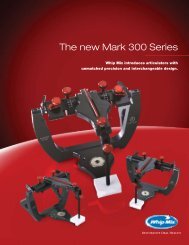
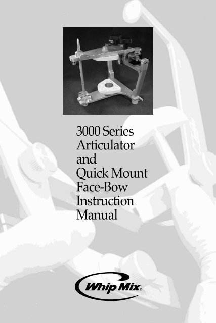
<strong>3000</strong> <strong>Series</strong><br />
<strong>Articulator</strong><br />
<strong>and</strong><br />
<strong>Quick</strong> <strong>Mount</strong><br />
<strong>Face</strong>-<strong>Bow</strong><br />
Instruction<br />
Manual
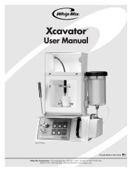
<strong>Whip</strong> <strong>Mix</strong> <strong>3000</strong> <strong>Series</strong> <strong>Articulator</strong>s<br />
Model 3040<br />
Model 3140<br />
2
CONTENTS<br />
INTRODUCTION 5<br />
OBTAINING FACE-BOW REGISTRATION 6<br />
I. Preparing The <strong>Face</strong>-<strong>Bow</strong> 6<br />
II. Preparing The <strong>Face</strong>-<strong>Bow</strong> Fork 7<br />
III. Positioning The <strong>Face</strong>-<strong>Bow</strong> On The Patient 9<br />
IV. Removing The <strong>Face</strong>-<strong>Bow</strong> From The Patient 12<br />
V. Obtaining Interocclusal Records 13<br />
DIRECT <strong>Mount</strong>ing THE MAXILLARY Cast On <strong>Series</strong> <strong>3000</strong> <strong>Articulator</strong>s 20<br />
I. Preparing The <strong>Articulator</strong> For <strong>Mount</strong>ing Casts 20<br />
II. Placing A Direct <strong>Mount</strong>ing <strong>Face</strong>-<strong>Bow</strong> On The <strong>Articulator</strong> 23<br />
III. <strong>Mount</strong>ing The Maxillary Cast With A Direct <strong>Mount</strong>ing <strong>Face</strong>-<strong>Bow</strong> 25<br />
INDIRECT <strong>Mount</strong>ing THE MAXILLARY Cast On <strong>Series</strong> <strong>3000</strong> <strong>Articulator</strong>s 28<br />
I. Preparing The <strong>Face</strong>-<strong>Bow</strong> And <strong>Articulator</strong> For <strong>Mount</strong>ing Casts 30<br />
II. Placing The <strong>Face</strong>-<strong>Bow</strong> Transfer Assembly On The <strong>Articulator</strong> 31<br />
III. <strong>Mount</strong>ing The Maxillary Cast 32<br />
<strong>Mount</strong>ing The M<strong>and</strong>ibular Cast 33<br />
Setting The Condylar Guidance Of The <strong>Articulator</strong> 36<br />
Technique For Fabrication Of A Custom Incisal Guide Table 42<br />
complete Denture Technique 43<br />
I. Constructing Occlusion Rims 43<br />
II. Preparing The <strong>Face</strong>-<strong>Bow</strong> Fork 43<br />
III. Preparing The <strong>Face</strong>-<strong>Bow</strong> Armamentarium 44<br />
IV. Positioning The <strong>Face</strong>-<strong>Bow</strong> 44<br />
V. Obtaining Interocclusal Records 45<br />
VI. Preparing The <strong>Articulator</strong> For <strong>Mount</strong>ing Casts 46<br />
VII. <strong>Mount</strong>ing The Maxillary Cast 46<br />
VIII. <strong>Mount</strong>ing The M<strong>and</strong>ibular Cast 48<br />
IX. Setting The Adjustable Incisal Guide Table 48<br />
3
X. Obtaining Protrusive Record 49<br />
XI. Fabricating A Remount Index 50<br />
XII. Remounting Casts 51<br />
XIII. Completed Dentures 51<br />
Interchangeability With SERIES <strong>3000</strong> <strong>Articulator</strong>s 52<br />
Reminders And Suggestions 53<br />
Maintenance 54<br />
SERIES <strong>3000</strong> ARTICULATORS PARTS LISTS 55<br />
Model 3040 <strong>Articulator</strong> 55<br />
Model 3140 <strong>Articulator</strong> 56<br />
WHIP MIX FACE-BOWS PARTS LISTS 57-60<br />
Model 8645 <strong>Face</strong>-<strong>Bow</strong> (For Direct <strong>Mount</strong>ing) 57<br />
Model 9600 <strong>Face</strong>-<strong>Bow</strong> (For Direct <strong>Mount</strong>ing) 58<br />
Models 9175/9185/9195 <strong>Face</strong>-<strong>Bow</strong>s (For Indirect <strong>Mount</strong>ing) 59<br />
Models 9275/9285/9295 <strong>Face</strong>-<strong>Bow</strong>s (For Indirect <strong>Mount</strong>ing) 60<br />
Bibliography 61<br />
4
INTRODUCTION<br />
WHIP MIX <strong>Articulator</strong>s <strong>and</strong> QUICK MOUNT <strong>Face</strong>-<strong>Bow</strong>s are designed to enable the user to quickly <strong>and</strong> easily<br />
mount casts of a patient’s dentition on a mechanical device that will reproduce their natural relationship<br />
<strong>and</strong> movements with an acceptable degree of accuracy. The simplicity <strong>and</strong> speed with which the necessary<br />
registrations are obtained <strong>and</strong> transferred to a WHIP MIX <strong>Articulator</strong> enable the operator to accomplish corrective<br />
<strong>and</strong> restorative dentistry with much greater precision than has ever before been possible without the use of<br />
expensive equipment <strong>and</strong> time consuming techniques.<br />
For those already using a fully adjustable instrument, a WHIP MIX <strong>Articulator</strong> serves as an excellent auxiliary<br />
instrument for diagnostic <strong>and</strong> patient education purposes, as well as constructing the clutches <strong>and</strong> recording<br />
devices needed to secure the proper recordings for setting the more complex instrument. Being arcon type<br />
instruments, WHIP MIX <strong>Articulator</strong>s are ideal for the study of occlusion <strong>and</strong> the movements of the temporom<strong>and</strong>ibular<br />
joints. With the condyle located on the lower frame <strong>and</strong> the guidance on the upper frame (arcon design), WHIP<br />
MIX semi-adjustable articulators have become the preferred choice of many teaching institutions. Advancing<br />
to a fully adjustable articulator becomes a much easier process after initial training on an arcon semi-adjustable<br />
articulator.<br />
<strong>Series</strong> <strong>3000</strong> <strong>Articulator</strong>s feature the same sturdy construction <strong>and</strong> reliability which have been demonstrated<br />
successfully in other WHIP MIX <strong>Articulator</strong> <strong>Series</strong>. In addition, the following innovative <strong>and</strong> useful features have<br />
been incorporated:<br />
• Ergonomic design with wide lingual access <strong>and</strong> ample interframe distance.<br />
• Tracking condylar guidance with progressive side shift capability.<br />
• An easily positioned centric latch provides a quick way<br />
to return to centric position.<br />
• A permanent intercondylar width of 110 mm — the same as the M setting<br />
found on other WHIP MIX <strong>Articulator</strong>s.<br />
• Elastics provide positive tracking of the condyles during excursive<br />
movements if secured.<br />
• Condyle release mechanisms to prevent accidental separation of the<br />
condyles from the tracking condylar guidance.<br />
• Non-skid rubber feet for stabilizing articulator when open<br />
WHIP MIX <strong>Series</strong> <strong>3000</strong> <strong>Articulator</strong>s feature the innovative ACCUMOUNT <strong>Mount</strong>ing System of interchangeability.<br />
This makes it possible to interchange mounted casts between any <strong>Series</strong> <strong>3000</strong> <strong>Articulator</strong> without loss<br />
of accuracy.<br />
As with other models in the WHIP MIX family of <strong>Articulator</strong>s, a variety of accessories are available. Each <strong>Series</strong><br />
<strong>3000</strong> <strong>Articulator</strong> is packaged with the following items:<br />
1 - Instruction Manual 1 - #8580B Plastic <strong>Mount</strong>ing Plate, Set of 2<br />
1 - Serial Number Card<br />
1 - #8580 Metal <strong>Mount</strong>ing Plate, Set of 2<br />
5
OBTAINING FACE-BOW REGISTRATION<br />
Fig. 1<br />
Items needed for a <strong>Face</strong>-<strong>Bow</strong> Registration:<br />
1. <strong>Face</strong>-<strong>Bow</strong> with Nasion Relator Assembly <strong>and</strong><br />
<strong>Face</strong>-<strong>Bow</strong> Fork (bite fork)<br />
2. Compound or Wax Registration Material<br />
3. Bard-Parker ® Blade or similar instrument<br />
I. Preparing <strong>Face</strong>-<strong>Bow</strong>s<br />
Fig. 2<br />
Clean <strong>and</strong> properly disinfect the plastic ear pieces before<br />
each use. If replacing them, make sure the hole on the flat<br />
side of each is above the side arm <strong>and</strong> the plastic is forced<br />
on until it touches the shoulder of the arm.<br />
Fig. 3<br />
A rubber b<strong>and</strong> may be easily positioned on the face-bow<br />
to aid in its manipulation.<br />
Note the caliper design of the QUICK MOUNT face-bow<br />
whereby the side arms move equal distances during the<br />
opening <strong>and</strong> closing motions.<br />
Fig. 4<br />
Slide the #8605A Nasion Relator Assembly until it is<br />
centered on the #8608 Cross Bar of the face-bow.<br />
6
Fig. 5<br />
Loosen the #8604 Thumb Screw on top of the face-bow. If<br />
using the <strong>Whip</strong> <strong>Mix</strong> metal face-bow you will need to loosen<br />
the three thumb screws on top of the face-bow.<br />
Fig. 6<br />
Loosen the #8640 T-Screw.<br />
Fig. 7<br />
Loosen the #8643 T-Screw.<br />
II. Preparing The <strong>Face</strong>-<strong>Bow</strong> Fork<br />
Fig. 8<br />
Make sure the bite fork has been properly sterilized.<br />
Low-heat impression compound, wax, or elastomeric are<br />
some of the materials which may be used as a bite<br />
registration medium for the bite fork. Elastomeric material<br />
is used in this demonstration due to its popularity.<br />
7
Fig. 9<br />
Place the elastomeric material uniformly over the top<br />
surface of the bite fork.<br />
Fig. 10<br />
Inspect the underside of the bite fork to ensure material<br />
is locked onto the bite fork via the retention holes.<br />
Fig. 11<br />
Position the bite fork so the mid-line of the bite fork<br />
aligns with the mid-line of the maxilla.<br />
Fig. 12<br />
Support the bite fork underneath by having the patient bite<br />
on cotton rolls. Some clinicians prefer to have the patient<br />
bite on the bite fork itself after registration material has been<br />
placed on both sides.<br />
Whichever registration technique is used, the goal is to<br />
record a shallow registration of the maxillary cusp tips.<br />
8
Fig. 13<br />
Inspect the registration for any soft tissue or deep<br />
occlusal registrations. Soft tissue registrations <strong>and</strong><br />
excess registration material may be easily cut away<br />
with a Bard-Parker ® Blade. Remember, it is only<br />
necessary to record the maxillary cusp tips!<br />
After trimming, place the registration back in the patient’s<br />
mouth <strong>and</strong> check for accuracy <strong>and</strong> stability.<br />
III. Positioning The <strong>Face</strong>-<strong>Bow</strong> On The Patient<br />
Fig. 14<br />
Before attempting to place the face-bow onto the bite fork,<br />
it is suggested the operator rehearse the following<br />
procedure with the patient. Caution the patient that the<br />
plastic ear pieces in the auditory canal will greatly amplify<br />
noises during the procedure.<br />
Fig. 15<br />
A finger cot placed over each ear piece will help facilitate<br />
proper disinfection of the face-bow.<br />
Remember, a rubber b<strong>and</strong> correctly placed will aid<br />
face-bow manipulation!<br />
9
Fig. 16<br />
With the bite fork repositioned in the patient’s mouth,<br />
have the patient grasp both arms of the face-bow <strong>and</strong><br />
bring them backwards to a position just forward of the<br />
patient’s ears. Then have the patient place each ear<br />
piece in the external auditory meatus <strong>and</strong> hold in place<br />
with a firm forward pressure.<br />
Fig. 17<br />
Start the #8642 Toggle onto the bite fork shaft <strong>and</strong> make<br />
sure each ear piece is securely positioned in the external<br />
auditory meatus <strong>and</strong> the horizontal cross bar is above<br />
the bite fork shaft.<br />
Fig. 18<br />
Push the toggle back on the fork shaft until it is near, but not<br />
touching, the lips.<br />
Fig. 19<br />
Center the plastic nose piece on the patient’s nasion <strong>and</strong><br />
exert firm pressure on the nose piece shaft while tightening<br />
the thumb screw of the nasion relator assembly.<br />
10
Fig. 20<br />
Tighten the center #8604 Thumb Screw on top of the<br />
face-bow.<br />
Fig. 21<br />
To prevent torquing of the face-bow <strong>and</strong> discomfort to the<br />
patient, support the face-bow with one h<strong>and</strong> <strong>and</strong> tighten<br />
the #8640 T-Screw.<br />
Fig. 22<br />
Next, tighten the #8643 T-Screw on the vertical bar, again<br />
taking care not to tilt the face-bow.<br />
110 mm<br />
Fig. 23<br />
A permanent intercondylar width of 110 mm is incorporated<br />
into all <strong>Series</strong> <strong>3000</strong> <strong>Articulator</strong>s. This corresponds to the “M”<br />
setting found on the face-bow.<br />
11
Fig. 24<br />
Therefore, when mounting a cast on a <strong>Series</strong> <strong>3000</strong><br />
<strong>Articulator</strong>, it is not necessary to record the intercondylar<br />
width marking designated by the S-M-L markings on the<br />
upper arm of the face-bow.<br />
IV. Removing The <strong>Face</strong>-<strong>Bow</strong> From<br />
The Patient<br />
Fig. 25<br />
Loosen the #8604 Thumb Screw on the nasion relator<br />
assembly <strong>and</strong> slide the nasion relator assembly away<br />
from the patient.<br />
Fig. 26<br />
Have the patient hold both arms of the face-bow <strong>and</strong> loosen<br />
the center thumb screw on top of the face-bow.<br />
Note: If using <strong>Whip</strong> <strong>Mix</strong> metal face-bow, loosen the three<br />
thumb screws located on the top.<br />
Fig. 27<br />
Advise the patient to gently pull the ear pieces out of<br />
his or her ears <strong>and</strong> help the patient carefully remove<br />
the face-bow with his or her mouth open. Now is a<br />
convenient time to take the interocclusal records<br />
necessary to mount the lower cast <strong>and</strong> set the condylar<br />
guidance of the articulator.<br />
12
V. Obtaining Interocclusal Records<br />
There are several materials available which may be used<br />
to make interocclusal records. There are also different<br />
techniques <strong>and</strong> philosophies for making these records.<br />
The material selected should complement the particular<br />
technique used. The technique suggested in this manual<br />
is but one method <strong>and</strong> <strong>Whip</strong> <strong>Mix</strong> does not imply that this is<br />
the only technique one can use.<br />
The following interocclusal records (check bites) may be<br />
utilized to program the condylar guidance of the articulator:<br />
• Centric Relation <strong>and</strong>/or Maximum Intercuspation<br />
• Right Lateral<br />
• Left Lateral<br />
• Protrusive (optional)<br />
Centric Relation Record<br />
Fig. 28<br />
Manipulate the m<strong>and</strong>ible into centric relation using your<br />
st<strong>and</strong>ard technique <strong>and</strong> slowly arc the m<strong>and</strong>ible closed<br />
until initial contact.<br />
Fig. 29<br />
Trim a wax record so it:<br />
a. Matches the buccal-to-buccal dimension of the<br />
patient’s maxillary arch, <strong>and</strong><br />
b. Covers only the posterior teeth.<br />
13
Fig. 30<br />
Warm the wax record in water until the tooth-contacting<br />
edges are soft enough to offer no resistance.<br />
Fig. 31<br />
Position the wax record against the maxillary posterior<br />
teeth. Do not press against the teeth or you may perforate<br />
the thin record.<br />
Fig. 32<br />
Manipulate the m<strong>and</strong>ible into centric relation. The maxillary<br />
<strong>and</strong> m<strong>and</strong>ibular posterior teeth will automatically create<br />
“cuspal indents” in the wax.<br />
Fig. 33<br />
Maintain this position while cooling the wax with a stream<br />
of air until the wax is no longer soft, then instruct the<br />
patient to “snap open.”<br />
14
Fig. 34<br />
Remove <strong>and</strong> examine the centric relation wax record for:<br />
a. The presence of adequate cuspal indents.<br />
b. The absence of wax perforation <strong>and</strong>/or soft<br />
tissue contact.<br />
Maximum Intercuspation Record<br />
Fig. 35<br />
Clinicians may choose to use any of the several techniques<br />
for obtaining maximum intercuspation records. Use of<br />
elastomeric material is demonstrated here.<br />
Fig. 36<br />
Have the patient close in the position of maximum<br />
intercuspation, <strong>and</strong> note the relative position of the teeth.<br />
Fig. 37<br />
Apply interocclusal registration material. Use enough<br />
material to cover the occlusal surfaces <strong>and</strong> incisal edges of<br />
the m<strong>and</strong>ibular teeth.<br />
15
Fig. 38<br />
Have the patient close into a position of maximum<br />
intercuspation <strong>and</strong> verify relative tooth position noted<br />
earlier. The maxillary <strong>and</strong> m<strong>and</strong>ibular posterior teeth<br />
will automatically create “cuspal indents” in the<br />
registration material.<br />
Fig. 39<br />
Maintain this position while the elastomer is setting. Remove<br />
<strong>and</strong> examine the maximum intercuspation wax record for:<br />
a. The presence of adequate cuspal indents.<br />
b. The absence of perforation, <strong>and</strong>/or soft<br />
tissue contact.<br />
Lateral Records<br />
Trim a wax record to the size of the centric relation record<br />
(refer to Section on Centric Relation Record).<br />
Fig. 40<br />
The thickness on the non-working side may have to be<br />
increased to achieve “cuspal indents” of the posterior teeth<br />
when the m<strong>and</strong>ible has moved 4–6 mm laterally from the<br />
centric relation position. Observe the interocclusal space<br />
with the m<strong>and</strong>ible in this position <strong>and</strong> use some of the<br />
previously trimmed excess wax to build up the required<br />
thickness if necessary.<br />
Warm the wax record in water until the tooth-contacting<br />
edges are soft enough to offer no resistance, then position<br />
the wax record against the maxillary posterior teeth. Do not<br />
press the record against the teeth or you may perforate the<br />
thin record.<br />
16
Fig. 41<br />
Manipulate the m<strong>and</strong>ible into centric relation <strong>and</strong> caution the<br />
patient to keep the teeth separated to avoid contact with the<br />
wax. Instruct the patient to slowly move the jaw toward his<br />
or her right shoulder. After moving 4–6 mm laterally, instruct<br />
the patient to close into the wax until “cuspal indents” have<br />
been created.<br />
Maintain this position while cooling the wax with a stream<br />
of air then instruct the patient to “snap open.” Remove <strong>and</strong><br />
examine the right lateral record for:<br />
a. The presence of adequate cuspal indents.<br />
b. The absence of wax perforation <strong>and</strong>/or soft<br />
tissue contact.<br />
Fig. 42<br />
Repeat this procedure for the left lateral record, having the<br />
patient move his or her jaw toward his or her left shoulder.<br />
Protrusive Record<br />
Trim a wax record to the size of the centric relation record<br />
(refer to section on Centric Relation Record).<br />
The thickness may have to be increased to achieve<br />
“cuspal indents” of the posterior teeth when the m<strong>and</strong>ible<br />
has been protruded 4–6 mm from the centric relation<br />
position. Observe the interocclusal space with the m<strong>and</strong>ible<br />
in this position <strong>and</strong> use some of the previously trimmed<br />
excess wax to build up the required thickness if necessary.<br />
Warm the wax record in water until the tooth-contacting<br />
edges are soft enough to offer no resistance, then position<br />
the wax record against the maxillary posterior teeth. Do not<br />
press the record against the teeth.<br />
17
Fig. 43<br />
Manipulate the m<strong>and</strong>ible into centric relation <strong>and</strong> caution<br />
the patient to keep his or her teeth separated to avoid<br />
contact with the wax. Instruct the patient to slowly move<br />
the m<strong>and</strong>ible straight forward. After the patient has<br />
protruded his or her m<strong>and</strong>ible 4–6 mm, verbally instruct<br />
the patient to close into the wax until “cuspal indents” have<br />
been created.<br />
Maintain this position while cooling the wax with a stream<br />
of air until the wax is no longer soft, then instruct the patient<br />
to “snap open.” Remove <strong>and</strong> examine the protrusive<br />
record for:<br />
a. The presence of adequate cuspal indents.<br />
b. The absence of wax perforation <strong>and</strong>/or soft<br />
tissue contact.<br />
Fig. 44<br />
Interocclusal wax records should always be used as soon as<br />
possible. Store the records in room temperature water until<br />
ready for use.<br />
Some clinicians prefer to utilize average settings for certain<br />
casework. The following figures are median values which<br />
may be taken into consideration when selecting appropriate<br />
average guidance figures: 1<br />
Immediate Side Shift<br />
Condylar Inclination 40°<br />
1.0 mm<br />
Registration material/wax records should be sterilized using<br />
an infection control spray.<br />
1<br />
Lundeen & Wirth, “Condylar Movement Patterns Engraved in Plastic Blocks,”<br />
Journal of Prosthetic Dentistry, Vol. 30, No. 6, pp. 866-875, 1973.<br />
18
DIRECT <strong>Mount</strong>ing THE MAXILLARY Cast<br />
On <strong>Series</strong> <strong>3000</strong> <strong>Articulator</strong>s<br />
I. Preparing The <strong>Articulator</strong> For<br />
<strong>Mount</strong>ing Casts<br />
Fig. 45<br />
Fig. 46<br />
The following items are needed for mounting casts on a<br />
<strong>Series</strong> <strong>3000</strong> <strong>Articulator</strong>:<br />
MOUNTING STONE or MOUNTING PLASTER<br />
Spatula<br />
Rubber <strong>Bow</strong>l<br />
<strong>Face</strong>-<strong>Bow</strong> Registration<br />
2 Clean <strong>Mount</strong>ing Plates<br />
Upper <strong>and</strong> Lower Casts<br />
Interocclusal Records<br />
Graduated Cylinder<br />
Plaster Knife<br />
Rubber B<strong>and</strong>s (Optional)<br />
Set the centric latch in the “open” position.<br />
Fig. 47<br />
Detach the #2426 Elastics from the lower frame by<br />
releasing the #2425 Catch from the #2413 Latch Block.<br />
Fig. 48<br />
Center the plastic incisal guide table so the rounded<br />
end of the incisal guide pin rests in the center of the table.<br />
20
Fig. 49<br />
Loosen the #8511 Incisal Guide Pin Screw.<br />
Fig. 50<br />
Remove or sufficiently raise the incisal guide pin so the<br />
upper member of the articulator will be able to rest on the<br />
horizontal crossbar of the face-bow.<br />
Fig. 51<br />
Press tab on condyle release to free condyle from<br />
condylar guide on the Model 3040.<br />
Fig. 52<br />
Each condylar guide assembly on the Model 3140<br />
<strong>Articulator</strong> does not have a condyle release mechanism<br />
because it features a half-tracking condylar guidance.<br />
21
Fig. 53<br />
Note: Set each condylar guide to 30° on the condylar<br />
inclination scale in preparation for attaching the face-bow<br />
assembly to the upper frame of the articulator.<br />
Fig. 54<br />
Tighten the black clamp knob while pressing the condylar<br />
guide assembly against the upper frame of the articulator.<br />
Fig. 55<br />
Set each progressive side shift guide setting to the “0” mark<br />
<strong>and</strong> tighten the side shift locking screw.<br />
Fig. 56<br />
Place clean <strong>Mount</strong>ing Plates on the upper <strong>and</strong> lower frames.<br />
The <strong>Quick</strong> Magnetic <strong>Mount</strong>ing System is shown here.<br />
22
Fig. 57<br />
Place metal disk into plastic mounting plate <strong>and</strong> attach to<br />
articulator.<br />
If using st<strong>and</strong>ard screw-type mounting plates, firmly tighten<br />
the #8508 <strong>Mount</strong>ing Plate knob when securing a mounting<br />
plate to the articulator.<br />
Fig. 58<br />
Two screw-type mounting plates are available.<br />
Plastic #8580B <strong>Mount</strong>ing Plates are an economical<br />
alternative to metal mounting plates. They are designed to<br />
be utilized for one case. Metal mounting plates are rigid <strong>and</strong><br />
reusable.<br />
The articulator is now ready to have the face-bow secured to<br />
its upper frame.<br />
II. Placing A Direct <strong>Mount</strong>ing <strong>Face</strong>-<strong>Bow</strong><br />
On The <strong>Articulator</strong><br />
Fig. 59<br />
Slide the plastic nasion relator assembly to the patients left,<br />
away from the center of the horizontal crossbar of the facebow<br />
if this has not already been done.<br />
Loosen the center thumb screw on the top of the face-bow.<br />
Note: A rubber b<strong>and</strong> properly positioned aids in manipulation.<br />
If using the original metal face-bow, loosen the three thumb<br />
screws on top of the face-bow.<br />
23
Fig. 60<br />
Hold the face-bow in one h<strong>and</strong> <strong>and</strong> the articulator in the other.<br />
Note: The rubber b<strong>and</strong> maintains the earpieces against<br />
the brass mounting pins with a slight pressure which helps<br />
facilitate stable placement of the face-bow on the articulator.<br />
Fig. 61<br />
Position the brass mounting pin located on the outer edge<br />
of the upright of the lower frame into the hole on the medial<br />
side of each plastic earpiece of the face-bow.<br />
Fig. 62<br />
While holding the left-bow against one’s body, make sure<br />
the right brass mounting pin fits securely into the hole in the<br />
right face-bow earpiece.<br />
Allow the anterior end of the upper frame of the articulator<br />
to rest on the horizontal crossbar of the face-bow.<br />
Securely tighten the thumb screw on top of the face-bow<br />
while still pressing the face-bow arms against one’s body.<br />
Fig. 63<br />
Make sure the articulator with attached face-bow is stable.<br />
You may want to use a face-bow fork support to stabilize<br />
maxillary cast during mounting procedures.<br />
24
Fig. 64<br />
Engage the centric latch for added stability.<br />
III. <strong>Mount</strong>ing The Maxillary Cast With<br />
A Direct <strong>Mount</strong>ing <strong>Face</strong>-<strong>Bow</strong><br />
Fig. 65<br />
Soak the cast in water for 3 to 4 minutes.<br />
Fig. 66<br />
For best orientation of the MOUNTING STONE to the cast,<br />
place indices on the top of the cast. Indices allow separation<br />
of cast from mounting with easy, accurate re-alignment.<br />
Fig. 67<br />
Seat the maxillary cast in the face-bow registration <strong>and</strong><br />
make sure it is stable with no rocking. The cast will need<br />
additional trimming if the upper frame will not close. An<br />
inaccurate mounting will result if the bite fork flexes during<br />
mounting.<br />
25
Fig. 68<br />
The #28706 <strong>Face</strong>-<strong>Bow</strong> Fork Support (shown here) is a<br />
convenient accessory used to support the bite fork during<br />
the mounting of the cast. The face-bow fork support<br />
attaches to the lower frame in place of the lower mounting<br />
plate. Its cross arm is raised to contact the under-surface<br />
of the face-bow fork to prevent flexing of the fork.<br />
Fig. 69<br />
<strong>Whip</strong> <strong>Mix</strong> MOUNTING STONE is ideal for mounting casts<br />
because it is formulated to have a short working time, great<br />
stacking ability <strong>and</strong> extremely low setting expansion.<br />
Lift the upper frame of the articulator <strong>and</strong> apply MOUNTING<br />
STONE to the base of the cast <strong>and</strong> the mounting plate.<br />
Fig. 70<br />
Close the upper frame to contact the cross bar, bringing the<br />
MOUNTING STONE on the two surfaces together. Do not use<br />
too thick a mix of MOUNTING STONE or attempt to apply<br />
force when the stone has already begun to set. Hold the<br />
upper frame in position until the MOUNTING STONE has set.<br />
Fig. 71<br />
Carefully remove the face-bow from the articulator.<br />
26
Fig. 72<br />
It is not necessary that the MOUNTING STONE be smooth<br />
<strong>and</strong> all voids filled with the first mix, but excess stone should<br />
be removed from the cast <strong>and</strong> articulator. Many clinicians<br />
prefer to utilize a second mix to fill the voids after the first<br />
mix has set.<br />
27
INDIRECT <strong>Mount</strong>ing THE MAXILLARY Cast<br />
Fig. 73<br />
<strong>Articulator</strong> <strong>Face</strong>-<strong>Bow</strong> Transfer<br />
Model # Model # Assembly #<br />
2240, 2340 9185 —<br />
3040, 3140 9185 9188<br />
8500 9195 9197<br />
.<br />
<strong>Whip</strong> <strong>Mix</strong> indirect mounting face-bows combine the<br />
face-bow registration technique of the traditional QUICK<br />
MOUNT face-bow with the many advantages of indirect<br />
mounting. The indirect mounting procedure offers the user<br />
more access, increased stability, greater ease of use, <strong>and</strong><br />
optimum instrument efficiency.<br />
Incorporating the indirect mounting technique does not<br />
require dramatic technique changes. The face-bow<br />
registration is taken on the patient utilizing the same<br />
technique as with the original <strong>Whip</strong> <strong>Mix</strong> QUICK MOUNT<br />
face-bow. Once the registration is obtained, the transfer<br />
assembly is removed from the face-bow <strong>and</strong> positioned<br />
onto the lower frame of the articulator.<br />
Fig. 74<br />
Indirect mounting face-bow used with the QUICK MOUNT<br />
Magnetic System.<br />
Fig. 75<br />
<strong>Whip</strong> <strong>Mix</strong> indirect mounting face-bows have been designed<br />
to be used with specific <strong>Whip</strong> <strong>Mix</strong> articulators as described<br />
in the chart. Additional transfer assemblies are available<br />
separately which allow the operator to mount one case <strong>and</strong>,<br />
with the aid of an additional transfer assembly, have the<br />
face-bow available for a second face-bow registration.<br />
Each transfer assembly includes:<br />
1 - <strong>Face</strong>-<strong>Bow</strong> Fork (#8609)<br />
1 - Vertical Rod with Horizontal Slide Bar,<br />
Toggles <strong>and</strong> “T” Screws<br />
1 - Support Bar (#8686)<br />
1 - <strong>Face</strong>-<strong>Bow</strong> Locking Screw (#8604)<br />
28
Fig. 76<br />
A<br />
A<br />
C<br />
C<br />
All <strong>Whip</strong> <strong>Mix</strong> QUICK MOUNT face-bows can be modified<br />
to have indirect mounting capability.<br />
The conversion package includes:<br />
B<br />
B<br />
A. Transfer Base Assembly (#9176Q, Figure 76 for the<br />
QUICK MOUNT magnet system) or (#1976A, Figure 77).<br />
B. Cross Bar (#8679)<br />
C. Transfer Assembly (see selection chart) Contains:<br />
• Locking Screw<br />
• Support Bar<br />
• <strong>Face</strong>-<strong>Bow</strong> Fork<br />
• Vertical Rod with Horizontal Slide Bar,<br />
Toggles <strong>and</strong> “T” Screws<br />
Fig. 77<br />
A<br />
C<br />
B<br />
Fig. 78<br />
Before using the indirect mounting face-bow, be sure the<br />
transfer assembly is oriented as pictured.<br />
Fig. 79<br />
Disinfect the face-bow <strong>and</strong> take a face-bow registration of<br />
the patient in the usual manner.<br />
29
I. Preparing The <strong>Face</strong>-<strong>Bow</strong> And<br />
<strong>Articulator</strong> For <strong>Mount</strong>ing Casts<br />
Fig. 80<br />
Remove the face-bow from the patient. Next, unscrew the<br />
#8604 Locking Screw on the cross bar to release the<br />
transfer assembly which holds the bite registration from<br />
the face-bow.<br />
Fig. 81<br />
Position the #8686 Support Bar onto the top of the transfer<br />
assembly <strong>and</strong> secure in place with the same #8604 Locking<br />
Screw.<br />
Remove the upper frame of the articulator from the lower<br />
frame <strong>and</strong> then remove the incisal guide pin.<br />
Fig. 82<br />
Place the #9176Q Transfer Base Assembly for the QUICK<br />
MOUNT magnetic system on the articulator. Secure the<br />
Transfer Base Assembly to the magnet using a metal disc.<br />
You may want to use the #28706 QUICK MOUNT magnetic<br />
system face-bow fork support as described in Figure 68.<br />
Fig. 83<br />
Note: All transfer base assemblies now have four holes. The<br />
extra set of holes allows the transfer base assemblies to be<br />
used on Hanau Wide Vue <strong>Articulator</strong>s with the appropriate<br />
<strong>Whip</strong> <strong>Mix</strong> Adaptor.<br />
30
II. Placing The <strong>Face</strong>-<strong>Bow</strong> Transfer<br />
Assembly On The <strong>Articulator</strong><br />
Fig. 84<br />
Insert the vertical rod of the transfer assembly into the<br />
transfer base <strong>and</strong> lower it until the bottom of the vertical<br />
rod contacts the transfer base.<br />
Fig. 85<br />
Tighten the #9184 Clamp Screw so the vertical rod fits<br />
securely in the transfer base. The transfer assembly should<br />
be oriented on the articulator as pictured.<br />
Fig. 86<br />
Place the upper frame of the articulator onto the lower<br />
frame, so the bottom of the metal boss now rests on the<br />
#8686 Support Bar.<br />
Fig. 87<br />
Engage the #2415 Latch <strong>and</strong> #2425 Catch on the<br />
articulator to keep the condyles in contact with the posterior<br />
<strong>and</strong> superior walls of the condylar guides.<br />
31
III. <strong>Mount</strong>ing The Maxillary Cast<br />
Fig. 88<br />
Properly support the bite fork as needed with a #28706<br />
<strong>Face</strong>-<strong>Bow</strong> Fork Support or other appropriate object.<br />
Position the cast into the bite registration.<br />
Fig. 89<br />
Apply <strong>Whip</strong> <strong>Mix</strong> MOUNTING STONE to the upper mounting<br />
plate <strong>and</strong> the top of the cast.<br />
Fig. 90<br />
Carefully hinge the upper frame so it contacts the top of the<br />
#8686 Support Bar. When the stone has set, remove the<br />
upper frame to allow removal of the transfer assembly <strong>and</strong><br />
transfer base.<br />
Fig. 91<br />
Replace the incisal guide pin in the upper frame, rounded<br />
end down, <strong>and</strong> reattach to lower frame.<br />
Fig. 9<br />
Place the mounting plate on the lower frame <strong>and</strong> proceed<br />
with the mounting of the lower cast as described in the next<br />
section of this <strong>Articulator</strong> Instruction Manual.<br />
32
<strong>Mount</strong>ing The M<strong>and</strong>ibular Cast<br />
Fig 93<br />
The upper <strong>and</strong> lower frames are made parallel by aligning<br />
the top of the pin boss with the dark line which completely<br />
encircles the pin. The pin, shown here at the zero mark,<br />
should be adjusted 3 to 5 millimeters above the zero mark<br />
to compensate for the thickness of the centric relation (CR)<br />
or maximum intercuspation (MI) registration used to mount<br />
the lower model.<br />
Fig. 94<br />
Make sure the #2415 Latch is engaged.<br />
Fig. 95<br />
Set both progressive side shift guides to the “0” position.<br />
Fig. 96<br />
Secure the elastics to the lower frame.<br />
33
Fig. 97<br />
Place the articulator upside-down. This positions the<br />
mounted cast with its occlusal surfaces upward. Check<br />
for complete seating — no rocking should occur.<br />
Fig. 98<br />
Place an interocclusal CR or MI registration on the maxillary<br />
cast. Make sure the record is completely seated.<br />
Make sure indices have been cut into the base of the<br />
m<strong>and</strong>ibular cast <strong>and</strong> it has been properly wetted prior to<br />
mounting.<br />
Fig. 99<br />
Position the cast on the CR or MI registration <strong>and</strong> check for<br />
stability. A variety of techniques <strong>and</strong> materials may be used<br />
to enhance stability.<br />
Fig. 100<br />
Hinge the lower frame into an open position <strong>and</strong> apply<br />
MOUNTING STONE to the base of the lower cast <strong>and</strong> the<br />
lower mounting plate.<br />
34
Fig. 101<br />
Hinge the lower frame closed until the incisal guide pin<br />
meets the incisal guide block. Make sure the condylar<br />
elements are seated flush against the posterior <strong>and</strong><br />
superior walls of the condylar guides. Carefully hold<br />
the articulator in this position until the MOUNTING STONE<br />
has set. Some clinicians like to use a rubber b<strong>and</strong> to stabilize<br />
the incisal guide pin against the incisal guide table.<br />
Fig. 102<br />
Once the initial mix of MOUNTING STONE has set, remove<br />
the material used to stabilize the cast. Prepare a second mix<br />
to fill any voids so an aesthetically pleasing product results.<br />
Fig. 103<br />
Finally, loosen the incisal guide pin screw <strong>and</strong> make sure the<br />
upper <strong>and</strong> lower casts contact. Retighten the incisal guide<br />
pin screw <strong>and</strong> make sure the incisal guide pin is positioned<br />
in the center of the incisal guide table. If a rubber b<strong>and</strong> has<br />
been used to help hold the upper <strong>and</strong> lower frame together,<br />
it should be removed so the upper <strong>and</strong> lower frames may be<br />
easily hinged open.<br />
35
Setting The Condylar Guidance Of The<br />
MODEL 3040 <strong>Articulator</strong><br />
Fig. 104<br />
After removing the CR or MI registration, release the<br />
centric latch.<br />
Fig. 105<br />
Release the elastics.<br />
Fig. 106<br />
Set both condylar guides to the 0° setting indicated on the<br />
condylar inclination scale — firmly tighten the left condylar<br />
guide locking screw <strong>and</strong> lightly secure the right condylar<br />
guide locking screw.<br />
Fig. 107<br />
Note: Set the progressive side shift guides to their<br />
most open position.<br />
36
Fig. 108<br />
Loosen the incisal guide pin screw. Raise the incisal guide<br />
pin to prevent any interference <strong>and</strong> retighten the screw.<br />
Fig. 109<br />
With the upper frame <strong>and</strong> its cast inverted, carefully seat the<br />
left lateral excursion interocclusal record on the maxillary cast.<br />
Fig. 110<br />
Lightly holding the articulator together, make sure the left<br />
condyle is seated “flush” against the rear wall. Gently seat<br />
the lower cast into the left lateral record <strong>and</strong> lightly hold the<br />
articulator <strong>and</strong> casts in position.<br />
Note: The teeth of the cast should seat evenly into the left<br />
lateral record. If the posterior teeth are raised out of the<br />
record, the condylar inclination needs to be decreased until<br />
the teeth are seated evenly in the record.<br />
Fig. 111<br />
To set the inclination of the right condylar guide, carefully<br />
loosen the #2432 Clamp Knob <strong>and</strong> rotate the guide until the<br />
teeth of the upper cast seat evenly in the left lateral record.<br />
It is advisable when making these adjustments that<br />
the contact should also be judged by sight, rather than<br />
depending solely on the sense of touch. This helps to ensure<br />
the casts are not forced out of position.<br />
37
Fig. 112<br />
Tighten the #2432 Clamp Knob to secure the guide<br />
into position. DO NOT USE EXCESSIVE PRESSURE<br />
when tightening the clamp knob.<br />
Fig. 113<br />
To set the right progressive side shift, loosen the right<br />
#8520A Side Shift Guide Locking Screw <strong>and</strong> move the<br />
#2405 Right Side Shift Guide until it touches the side of<br />
the condyle element.<br />
Retighten the right #8520A Screw.<br />
Fig. 114<br />
Record the amount of condylar inclination <strong>and</strong><br />
progressive side shift found on the Patient<br />
Registration Card.<br />
Patient Record Card For Models 8500, 3040, 3140.<br />
38
Fig. 115<br />
After the right condylar guidance has been recorded, the<br />
condylar guidance should be neutralized as previously<br />
described. Next, the left condylar guidance is adjusted using<br />
the right lateral excursion record <strong>and</strong> repeating the above<br />
procedure.<br />
Fig. 116<br />
Many wish to set the condylar inclination of the articulator<br />
with a protrusive record. To utilize the protrusive record,<br />
first neutralize the condylar inclination <strong>and</strong> progressive side<br />
shift settings. Place the protrusive record on the inverted<br />
upper frame of the articulator <strong>and</strong> gently seat the lower<br />
cast into the protrusive record.<br />
Both condylar elements will have moved away from<br />
the posterior surfaces of their respective condylar guides.<br />
Fig. 117<br />
Using sight <strong>and</strong> touch, rotate the left condylar guide until<br />
the teeth on the left side of the upper cast seat evenly into<br />
the protrusive record, then tighten the #2432 Clamp Knob.<br />
Record the reading <strong>and</strong> repeat the procedure on the right<br />
side. Note: The lateral records are used to determine the<br />
progressive side shift settings.<br />
Fig. 118<br />
The mounted case on a Model 3040 <strong>Articulator</strong>.<br />
39
SeTTING THE CONDYLAR GUIDANCE OF THE<br />
MODEL 3140 ARTICULATOR<br />
Fig. 119<br />
Follow the technique recommended for setting the condylar<br />
guidance of the Model 3040 <strong>Articulator</strong>, Fig. 104–118<br />
(p. 36–39). Next, with the upper frame <strong>and</strong> its cast inverted,<br />
carefully seat the right lateral interocclusal record on the<br />
upper cast. Holding the upper frame with one h<strong>and</strong> <strong>and</strong> the<br />
lower frame in the other, place the right (working) condylar<br />
element in the right condylar guide. Make sure the right<br />
condyle element is seated “flush” against the rear wall.<br />
Gently seat the lower cast into the right lateral record <strong>and</strong><br />
tightly hold the articulator <strong>and</strong> casts in position on the right side.<br />
Fig. 120<br />
Notice that the left condylar element has moved away from<br />
both the superior <strong>and</strong> posterior surface of the condylar guide<br />
<strong>and</strong> toward the medial wall.<br />
Fig. 121<br />
To set the inclination of the left condylar guide, carefully<br />
loosen its clamp knob <strong>and</strong> rotate the guide until the superior<br />
wall touches the condyle element.<br />
It is advisable when making these adjustments, that the<br />
contact should also be judged by sight, rather than<br />
depending solely on the sense of touch. This helps to<br />
ensure that the casts are not forced out of position.<br />
Fig. 122<br />
Tighten the #2432 Clamp Knob to secure the guide in<br />
position. DO NOT USE EXCESSIVE PRESSURE when<br />
tightening the clamp knob.<br />
40
Fig. 123<br />
To set the left progressive side shift guide, loosen the left<br />
#8520A Locking Screw <strong>and</strong> move the #2406 Left Side Shift<br />
Guide until it touches the side of the condyle element <strong>and</strong><br />
retighten the #8520A Locking Screw.<br />
Fig. 124<br />
After the left condylar guidance has been recorded, the<br />
condylar guidance should be neutralized as previously<br />
described. Next, the right condylar guidance is adjusted<br />
using the left lateral excursion record <strong>and</strong> repeating the<br />
above procedure.<br />
Fig. 125<br />
Many wish to set the condylar inclination of the articulator<br />
with a protrusive record. To utilize the protrusive record, first<br />
neutralize the condylar inclination <strong>and</strong> progressive side shift<br />
settings. Place the protrusive record on the inverted upper<br />
frame of the articulator <strong>and</strong> gently seat the lower cast into<br />
the protrusive record. Both condylar elements will have<br />
moved away from the posterior <strong>and</strong> superior surfaces of<br />
their respective condylar guide assemblies.<br />
Fig. 126<br />
Using sight <strong>and</strong> touch, rotate the right condylar guide until<br />
it contacts the condylar ball, then tighten the #2432 Clamp<br />
Knob. Record the reading <strong>and</strong> repeat the procedure on the<br />
left side. The right <strong>and</strong> left lateral records are then used to<br />
determine the progressive side shift settings.<br />
41
Fig. 127<br />
To prevent possible wearing away of the stone casts during<br />
manipulation of the articulator, or to make a permanent<br />
record of a specific case, the natural incisal guidance may<br />
be recorded. This is done by adding a layer of self-curing<br />
resin to the #8526F Plastic Incisal Guide Table <strong>and</strong> forming<br />
the guidance path into the resin as it cures.<br />
Figure shows materials needed for fabrication of a custom<br />
incisal guide table.<br />
Fig. 128<br />
1. Raise the incisal guide pin 1–2 mm.<br />
2. Lubricate the rounded end of the incisal guide pin.<br />
Next, moisten the surface of the incisal guide table<br />
with 1–2 drops of self-curing acrylic monomer.<br />
3. <strong>Mix</strong> enough acrylic to place approximately 1/4” on<br />
the top of the incisal guide table.<br />
4. Once the acrylic is in a doughy state, place the<br />
acrylic on the table.<br />
Fig. 129<br />
5. Carefully, close the articulator in centric position.<br />
6. Move the upper frame of the articulator back to simulate<br />
a straight protrusive movement (end to end).<br />
7. From centric, move the upper member of the articulator<br />
to give a straight right lateral movement.<br />
8. Then, move the upper member of the articulator to<br />
give a straight left lateral movement.<br />
9. Move through all intermediate excursions between<br />
the lateral <strong>and</strong> protrusive positions. Allow the acrylic<br />
to harden <strong>and</strong> trim off excess acrylic.<br />
Fig. 130<br />
The #8533 Dovetail Incisal Block is a convenient<br />
accessory designed so a custom acrylic guide may be<br />
easily removed <strong>and</strong> can later be easily replaced. Its<br />
dovetail sides <strong>and</strong> centering screw assure the user of<br />
accurate repositioning time after time.<br />
42
COMPLETE Denture Technique<br />
(shown on Model 2240 <strong>Articulator</strong>)<br />
I. Constructing Occlusion Rims<br />
Fig. 131<br />
Having obtained a master cast, wax occlusion rims should<br />
be formed on well-adapted record bases (base plates) for<br />
the upper <strong>and</strong> lower arches. After examination of the upper<br />
record base in the patient’s mouth, adjust the base plate, if<br />
necessary.<br />
Contour the upper <strong>and</strong> lower occlusion rims, establish<br />
occlusal vertical dimension <strong>and</strong> plane of orientation.<br />
Fig. 132<br />
Create wedge-shaped V indices in the wax occlusion rims.<br />
II. Preparing The <strong>Face</strong>-<strong>Bow</strong> Fork<br />
Fig. 133<br />
Apply vinylpolysiloxane (VPS) adhesive to a properly sterilized<br />
bite fork.<br />
Note: Adhesive not m<strong>and</strong>atory when using perforated bite fork.<br />
Fig. 134<br />
Some clinicians prefer to utilize a pronged bite fork.<br />
43
III. Preparing <strong>Face</strong>-<strong>Bow</strong> Armamentarium<br />
Follow the same procedure as that outlined earlier on pages 6-7.<br />
IV. Positioning <strong>Face</strong>-<strong>Bow</strong><br />
Fig. 135<br />
Extraorally, record the maxillary wax rim indices onto the bite<br />
fork using VPS. Make sure the mid-line of the palate <strong>and</strong> the<br />
stem of the bite fork are properly aligned.<br />
Fig. 136<br />
Place bite fork/wax rim assembly into patient’s mouth.<br />
Fig. 137<br />
Position the face-bow onto the patient as described on<br />
pages 9-12.<br />
Fig. 138<br />
Tighten the thumb screw on top of the face-bow.<br />
44
Fig.139<br />
Tighten the T-screw on the horizontal bar first. Next, tighten<br />
the T-screw on the vertical bar.<br />
Fig. 140<br />
Once the face-bow record has been made, remove the wax<br />
rim <strong>and</strong> record base from the bite fork registration. Set aside<br />
the face-bow assembly for later mounting.<br />
V. Obtaining Interocclusal Records<br />
Fig. 141<br />
To make the jaw relation record, a vinylpolysiloxane<br />
registration material or other appropriate record medium<br />
is placed onto the V-indices of the wax rim.<br />
Fig. 142<br />
The patient is guided into centric relation <strong>and</strong> is allowed to<br />
close until the wax rims come into contact. The registration<br />
material is allowed to set <strong>and</strong> is then removed.<br />
45
VI. Preparing The <strong>Articulator</strong> For<br />
<strong>Mount</strong>ing Casts<br />
Fig. 143<br />
Many operators prefer to replace the plastic incisal guide<br />
block with an adjustable metal table, such as the #2460<br />
Adjustable Guide Table (shown).<br />
Fig. 144<br />
To install the adjustable guide table, remove the #8526F<br />
Plastic Incisal Guide from the articulator. Slide the adjustable<br />
table into the thumb screw slot in the lower frame of the<br />
articulator <strong>and</strong> tighten the thumb screw.<br />
Fig. 145<br />
Adjust the position of the adjustable guide table until the<br />
chiseled end of the incisal guide pin lies directly over the<br />
scribed line on the guide table.<br />
Note: Guide pin must be set at “0” on upper member.<br />
VII. <strong>Mount</strong>ing The Maxillary Cast<br />
Fig. 146<br />
The indirect technique of mounting the maxillary cast will be<br />
demonstrated. However, the direct mounting technique may<br />
also be used to mount the maxillary edentulous cast.<br />
The transfer assembly has been removed from the face-bow<br />
<strong>and</strong> the support bar is placed into position.<br />
46
Fig. 147<br />
The QUICK MOUNT transfer base has been placed onto the<br />
lower member of the articulator <strong>and</strong> is held in position by<br />
the QUICK MOUNT cast support. The transfer assembly is<br />
inserted into the transfer base <strong>and</strong> the clamp is securely<br />
tightened.<br />
Fig. 148<br />
The QUICK MOUNT cast support is adjusted until it lightly<br />
makes contact with the bottom of the bite fork.<br />
Fig. 149<br />
The cast is placed into the occlusion rim, which is then<br />
seated into the registration on the bite fork. The assembly<br />
is now completed <strong>and</strong> ready for the addition of <strong>Whip</strong> <strong>Mix</strong><br />
MOUNTING STONE.<br />
Fig. 150<br />
The completed mounted maxillary cast. The transfer<br />
assembly <strong>and</strong> transfer base may be removed <strong>and</strong> the<br />
incisal guide pin replaced.<br />
47
VIII. <strong>Mount</strong>ing The M<strong>and</strong>ibular Cast<br />
Fig. 151<br />
Place the jaw relation records between the wax occlusion<br />
rims. Be certain the casts or record bases are not in contact<br />
with one another. Casts may be secured in this position by<br />
using rigid wire <strong>and</strong> sticky wax.<br />
Fig. 152<br />
The mounted maxillary <strong>and</strong> the affixed m<strong>and</strong>ibular casts can<br />
now be placed on the articulator. The casts <strong>and</strong> articulator<br />
are inverted <strong>and</strong> <strong>Whip</strong> <strong>Mix</strong> MOUNTING STONE is added.<br />
Fig. 153<br />
The mounting is complete. Additional jaw relation records<br />
can verify its accuracy. Accurate fit of the verification records<br />
into the V-shaped indices will denote a precise mounting.<br />
IX. Setting the Adjustable Incisal Guide<br />
Table<br />
After the anterior denture teeth are positioned, the<br />
adjustable guide table may be set.<br />
Fig. 154<br />
Loosen the thumb screw of the incisal guide table <strong>and</strong> bring<br />
the anterior teeth into edge-to-edge contact.<br />
48
Fig. 155<br />
Adjust the inclination of the guide table until it contacts the<br />
incisal pin, then retighten the thumb screw.<br />
Fig. 156<br />
Move the teeth into a left lateral relation.<br />
Fig. 157<br />
Loosen the thumb screw <strong>and</strong> raise the right wing of the table<br />
until it touches the chisel end of the guide pin. Tighten the<br />
thumb screw to secure this position <strong>and</strong> repeat the same<br />
operation for the left wing with the teeth in a right lateral<br />
position.<br />
X. Obtaining Protrusive Record<br />
Fig. 158<br />
The aesthetic try-in appointment affords the clinician the<br />
ability to verify tooth setup <strong>and</strong> obtain a well-indexed<br />
protrusive record. The record should be created at an<br />
extended protrusive position to allow for bilateral condylar<br />
movement.<br />
49
Fig. 159<br />
Set condylar inclinations on the articulator as described<br />
previously on pages 36-41.<br />
XI. Fabricating A Remount Index<br />
Fig. 160<br />
After denture processing, replace the maxillary denture <strong>and</strong><br />
cast onto the indexed mounting. Replace the mounting, cast,<br />
<strong>and</strong> denture onto the articulator. Attach the QUICK MOUNT<br />
remount jig to the lower frame.<br />
Fig. 161<br />
Add sufficient stone to the remount jig to index only the cusp<br />
tips of the denture teeth.<br />
Fig. 162<br />
The completed remount index.<br />
50
XII. Remounting Casts<br />
Fig. 163<br />
After the dentures have been polished, the maxillary denture<br />
can be mounted to the articulator in anticipation of a clinical<br />
remount to evaluate the denture occlusion.<br />
Obtain remount casts. Using the remount index, mount the<br />
maxillary denture <strong>and</strong> remount cast to the articulator.<br />
Fig. 164<br />
During the clinical placement of the dentures following<br />
adjustment of tissue surfaces, new centric relation records<br />
are made <strong>and</strong> used to mount the m<strong>and</strong>ibular denture <strong>and</strong><br />
remount cast. The denture occlusion may be evaluated <strong>and</strong><br />
adjusted as needed.<br />
XIII. Completed Dentures<br />
Fig. 165<br />
The patient <strong>and</strong> her completed dentures.<br />
51
Interchangeability With The Model 3040 <strong>Articulator</strong><br />
All <strong>Series</strong> <strong>3000</strong> <strong>Articulator</strong>s feature the ACCUMOUNT <strong>Mount</strong>ing System. The ACCUMOUNT<br />
System makes it possible for the dental practitioner <strong>and</strong> the dental laboratory to interchange<br />
casts without exchanging articulators.<br />
Features And Advantages<br />
1. When clinicians <strong>and</strong> dental students use a dental laboratory that has a <strong>Series</strong> <strong>3000</strong> <strong>Articulator</strong>,<br />
casts need no longer be mounted on an articulator when shipped to such laboratory.<br />
2. Clinicians can purchase fewer instruments while maintaining the same level<br />
of care for their patients.<br />
3. Instrument damage caused by shipping the articulator to <strong>and</strong> from the dental lab is eliminated.<br />
4. Precise alignment of the upper <strong>and</strong> lower frames is checked at the factory prior to shipping.<br />
52
Reminders And Suggestions<br />
1. When securing interocclusal records to be used in mounting casts <strong>and</strong> setting the articulator,<br />
never allow the teeth to penetrate the recording material (impression compound, wax,<br />
gypsum, impression paste, etc.) too deeply. They should never contact the opposing teeth,<br />
the metal face-bow fork, or any firm material that may be used as a carrying tray or h<strong>and</strong>le.<br />
Any record showing evidence of penetration should be discarded <strong>and</strong> remade.<br />
2. The more stable a recording material is, the more it will resist distortion during its later<br />
use. Any such material should be in a very soft state, however, during the initial recording<br />
procedure.<br />
3. The following technique may be used to secure interocclusal records of partially edentulous<br />
patients.<br />
If natural dentition opposes the edentulous space, the partial occlusion rim is built up to<br />
nearly touch the opposing teeth. Zinc oxide <strong>and</strong> eugenol impression paste is then added to<br />
the surface of the occlusion rim of sufficient depth to register the tips of the opposing teeth<br />
when brought into the desired relationship.<br />
When the opposing spaces are both edentulous, one occlusion rim is built up in the customary<br />
manner to near the occlusal plane, while the opposing rim is built to near this plane with<br />
small cones of hard wax (or plastic) to indicate the registration in the impression paste.<br />
When absence of teeth makes it necessary to obtain interocclusal records on partial<br />
occlusion rims, these records must be made with the supporting soft tissue in as near a static<br />
condition as is possible; some combination of these ideas can be planned to accomplish<br />
this with acceptable accuracy.<br />
4. With casts of unusually thin vertical dimensions, which would necessitate the use of a great<br />
bulk of MOUNTING STONE, it is suggested the mounting plate be built up to near the correct<br />
thickness with a mix of MOUNTING STONE. This mix should be allowed to set for 20 minutes<br />
or longer before the actual mounting procedure is performed.<br />
5. For each <strong>Series</strong> <strong>3000</strong> <strong>Articulator</strong>, make a split cast mounting on the articulator before mounting<br />
the first case. This will be used for reference purposes should the articulator ever be dropped<br />
or mish<strong>and</strong>led. If the split cast mounting ever shows any discrepancy, return the articulator<br />
to the dealer for factory recalibration at a nominal charge.<br />
53
Maintenance<br />
The <strong>Whip</strong> <strong>Mix</strong> Model 3040 <strong>Articulator</strong> is a sturdily constructed instrument that will provide many<br />
years of service with reasonable care. Both the upper <strong>and</strong> lower frames are made of cast aluminum.<br />
All aluminum parts are anodized to prevent corrosion or staining. Each condyle element consists of<br />
a stainless steel shaft <strong>and</strong> a durable plastic condyle ball. The condylar guide assemblies are made<br />
of anodized aluminum.<br />
• Do not attempt to dislodge or remove the condyle ball from the condyle element<br />
shaft.<br />
• The sealing compound placed over the #2414 Latch Block <strong>Mount</strong>ing Screw,<br />
#4415 Set Screws, #8548 Set Screws, <strong>and</strong> #8507 Screw should not be<br />
disturbed.<br />
• Do not attempt to remove the #2428 Screws holding each condyle release<br />
mechanism.<br />
• Avoid getting wax or stone in the screw holes which may damage the threads.<br />
• Tighten screws snugly, but not too tightly. Overtightening the retaining screws can<br />
strip the threads.<br />
• It is a good idea to use a carrying case when the articulator is transported.<br />
Dropping the articulator may result in bent or broken parts which may affect the<br />
articulator’s ability to accurately reproduce a patient’s m<strong>and</strong>ibular movements.<br />
• A thin film of lubricant (<strong>Whip</strong> <strong>Mix</strong> LUBRIPLATE) or silicone spray<br />
applied to the surfaces upon which the condylar elements move<br />
will provide a smooth action of these parts.<br />
• Failing to remove excess stone, or not keeping the articulator clean may result in<br />
corrosion of articulator surfaces.<br />
• Apply silicone spray to articulator frame to prevent plaster or stone from<br />
sticking to surfaces.<br />
54
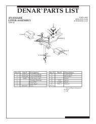
SERIES <strong>3000</strong> ARTICULATOR PARTS LIST<br />
Model 3040<br />
<strong>Articulator</strong><br />
# PART# QTY. DESCRIPTION<br />
1 MA8506 2 LEG SCREW<br />
2 MA8505 2 LEG<br />
3 MA8343 1 LOWER FRAME<br />
4 ma8527 1 SCREW<br />
5 ma8526F 1 INCISAL GUIDE<br />
6 ma2407 1 GUIDE PIN<br />
7 ma2423 1 LATCH BLOCK<br />
8 ma2414 1 button head SCREW<br />
9 ma2415 1 LATCH<br />
10 ma2437 1 SCREW<br />
11 ma2416 1 Latch Rod<br />
12 ma2421 1 Upright<br />
13 ma2408 2 Condyle Element<br />
14 ma2438 2 Set Screw<br />
15 ma2406 1 Side Shift Left<br />
16 ma2405 1 Side Shift Right (as shown)<br />
17 ma8520A 2 Locking Screw<br />
18 ma8547 2 Fibre Washer<br />
19 ma2451 1 Condylar Guide Right<br />
(as shown)<br />
20 ma2452 1 Condylar Guide Left<br />
21 ma2418 2 Spring<br />
22 ma2428 4 Screw<br />
23 ma2453 1 Anterior Stop – Right<br />
24 ma2454 1 Anterior Stop – Left<br />
25 ma2422 2 Hex Screw<br />
26 ma2432 2 clamp knob<br />
27 ma2424 2 Washer<br />
28 ma2401 1 Upper Frame<br />
29 ma8507 1 Screw<br />
30 ma8545 2 Steel Washer<br />
31 ma2410 1 Guide Pin Boss<br />
32 ma8511 1 Guide Pin Screw<br />
33 ma8810 2 Pin<br />
34 ma8546 2 Fibre Washer<br />
35 ma8508 2 Knob<br />
36 ma8548 2 Set Screw<br />
37 ma8519 2 <strong>Face</strong>-bow mounting pin<br />
38 ma2419 1 Black Plastic Cap<br />
39 ma2409 1 O Ring<br />
40 ma2425 1 Catch<br />
41 ma2426 2 Elastic<br />
42 ma2427 2 Spring Shield<br />
43 MA2242 1 <strong>Mount</strong>ing Plate Screw<br />
44 ma8509 2 <strong>Mount</strong>ing Plate Pin<br />
45 MA8344 1 <strong>Mount</strong>ing Table<br />
47 MA8543 3 foot bumper<br />
48 MA2444 1 boss<br />
49 ma2435 1 screw<br />
55
Model 3140<br />
<strong>Articulator</strong><br />
# PART# QTY. DESCRIPTION<br />
1 MA8506 2 LEG SCREW<br />
2 ma8505 2 LEG<br />
3 ma8343 1 LOWER FRAME<br />
4 ma8527 1 SCREW<br />
5 ma8526F 1 INCISAL GUIDE<br />
6 ma2407 1 GUIDE PIN<br />
7 ma2423 1 LATCH BLOCK<br />
8 ma2414 1 button head screw<br />
9 ma2415 1 LATCH<br />
10 ma2437 1 SCREW<br />
11 ma2416 1 Latch Rod<br />
12 ma2421 1 Upright<br />
13 ma2408 2 Condyle Element<br />
14 ma2438 2 Set Screw<br />
15 ma2406 1 Side Shift Left<br />
16 ma2405 1 Side Shift Right (as shown)<br />
17 ma8520A 2 Locking Screw<br />
18 ma8547 2 Fibre Washer<br />
19 ma2448 1 Condylar Guide Right<br />
(as shown)<br />
20 ma2449 1 Condylar Guide Left<br />
21 ma2422 2 Hex Screw<br />
22 ma2432 2 clamp knob<br />
23 ma2424 2 Washer<br />
24 ma2401 1 Upper Frame<br />
25 ma8507 1 Screw<br />
26 ma8545 2 Steel Washer<br />
27 ma2410 1 Guide Pin Boss<br />
28 ma8511 1 Guide Pin Screw<br />
29 ma8810 2 Pin<br />
30 ma8546 2 Fibre Washer<br />
31 ma8508 2 Knob<br />
32 ma8548 2 Set Screw<br />
33 ma8519 2 <strong>Face</strong>-bow mounting pin<br />
34 ma2419 1 Black Plastic Cap<br />
35 ma2409 1 O Ring<br />
36 ma2425 1 Catch<br />
37 ma2426 2 Elastic<br />
38 MA2242 1 <strong>Mount</strong>ing Plate Screw<br />
39 ma8509 2 <strong>Mount</strong>ing Plate Pin<br />
40 ma8344 1 <strong>Mount</strong>ing Table<br />
42 ma8543 3 foot bumper<br />
43 ma2444 1 boss<br />
49 ma2435 1 screw<br />
56
WHIP MIX FACE-BOWS PARTS LISTS<br />
Model 8645<br />
face-bow<br />
FOR DIRECT MOUNTING<br />
# PART# QTY. DESCRlPTlON<br />
1 ma8640 1 T-screw<br />
2 ma8643 1 t-screw<br />
3 ma2424 1 washer nylon<br />
4 ma8617 1 screw<br />
5 ma8644 1 horizontal clamp rod<br />
6 ma8608 1 slide bar assembly<br />
7 ma8601 1 face-bow (right)<br />
8 ma8603r 1 ear piece (right)<br />
9 ma8603l 1 ear piece (left)<br />
10 ma8602 1 face-bow (left)<br />
11 ma8604 3 locking screw<br />
12 ma8607 1 nose block<br />
13 ma8622 1 screw for upright post<br />
14 ma8606 1 nose piece shaft<br />
15 ma8605 1 upright post<br />
16 ma8609 1 bite fork<br />
17 ma8619 2 retaining ring<br />
18 ma8641 1 toggle<br />
19 ma8616 1 lock washer<br />
20 ma8642 1 toggle<br />
NOT ma8549 PKG. OF 6 RUBBER<br />
SHOWN<br />
BANDS<br />
57
model 9600<br />
face-bow<br />
For Direct <strong>Mount</strong>ing<br />
# PART# QTY. DESCRlPTlON<br />
1 ma8640 1 T-SCREW<br />
2 ma8643 1 T-SCREW<br />
3 ma8617 1 SCREW<br />
4 ma2424 1 washer nylon<br />
5 ma8644 1 HORIZONTAL CLAMP rod<br />
6 ma8609 1 BITE FORK<br />
7 ma8608 1 slide bar assembly<br />
8 ma9605 1 nut<br />
9 ma9601-1 1 FACE-BOW (RIGHT)<br />
10 ma8603r 1 ear piece (right)<br />
11 ma8603l 1 ear piece (left)<br />
12 ma9606a 3 screw<br />
13 ma9602-1 1 FACE-BOW (LEFT)<br />
14 ma8607 1 nose block<br />
15 ma8622 1 screw for upright post<br />
16 ma8606 1 nose piece shaft<br />
17 ma8619 2 retaining ring<br />
18 ma8605 1 upright post<br />
19 ma8641 1 toggle<br />
20 ma8616 1 lock washer<br />
21 ma8642 1 toggle<br />
22 ma8603a 1 ear piece soft set<br />
NOT ma8549 PKG. OF 6 RUBBER<br />
SHOWN<br />
BANDS<br />
58
MODELS 9175/<br />
9185/9195<br />
FACE-BOWS<br />
FOR INDIRECT MOUNTING<br />
WITH DB2000/2200/9000/9800<br />
ARTICULATORS<br />
# PART# QTY. DESCRlPTlON<br />
1 ma9180 1 SCREW, rd head<br />
2 ma9183 1 CLAMP<br />
3 ma9182 1 FIXED CLAMP<br />
4 ma2424 1 WASHER nylon<br />
5 ma9176 1 TRANSFER BASE<br />
6 ma8644 1 HORIZONTAL<br />
CLAMP rod<br />
7 ma8609 1 BITE FORK<br />
8 ma9177 1 VERTICAL ROD FOR<br />
#ma9175 FACE-BOW<br />
ma9187 1 VERTICAL ROD FOR<br />
#MA9185 FACE-BOW<br />
ma9196 1 VERTICAL ROD FOR<br />
#MA9195 FACE-BOW<br />
9 ma8686 1 SUPPORT BAR<br />
10 ma8679 1 CROSS BAR<br />
11 ma8601 1 FACE-BOW (RIGHT)<br />
12 ma8603r 1 ear piece (right)<br />
13 ma8603l 1 ear piece (left)<br />
14 ma8604 4 locking screw<br />
15 MA8602 1 FACE-BOW (LEFT)<br />
16 MA8622 1 SCREW FOR<br />
UPRIGHT POST<br />
17 MA8607 1 NOSE BLOCK<br />
18 MA8606 1 NOSE PIECE SHAFT<br />
19 MA8605 1 UPRIGHT POST<br />
20 MA8619 3 RETAINING RING<br />
21 MA8641 1 TOGGLE CLAMP<br />
22 MA8616 1 LOCK WASHER<br />
23 MA8642 1 TOGGLE CLAMP<br />
24 MA8643 1 T-SCREW<br />
25 MA8640 1 T-SCREW<br />
26 MA9184 1 CLAMP SCREW<br />
NOT MA8549 PKG. OF 6 RUBBER<br />
SHOWN<br />
BANDS<br />
59
MODELS 9275/<br />
9285/9295<br />
FACE-BOWS<br />
FOR INDIRECT MOUNTING<br />
WITH 2240/2340/8340 ARTICULA-<br />
TORS<br />
(PLASTIC EAR BOW)<br />
# PART# QTY. DESCRlPTlON<br />
1 MA9180 1 SCREW, RD HEAD<br />
2 MA9183 1 CLAMP<br />
3 MA9182 1 FIXED CLAMP<br />
4 MA9176 1 TRANSFER BASE<br />
5 MA2424 1 WASHER NYLON<br />
6 MA8644 1 HORIZONTAL<br />
CLAMP ROD<br />
7 MA8609 1 BITE FORK<br />
8 MA9610 1 CROSS BAR ASSEMBLY<br />
9 MA8604 1 LOCKING SCREW<br />
10 MA8606 1 NOSE PIECE SHAFT<br />
11 MA8607 1 NOSE BLOCK<br />
12 MA9608 4 WASHER NYLON<br />
13 MA9607 2 SCREW BUTTON HEAD<br />
14 MA9601-1 1 FACE-BOW (RIGHT)<br />
15 MA8903R 1 EAR PIECE (RIGHT)<br />
16 MA8603L 1 EAR PIECE (LEFT)<br />
17 MA9602-1 1 FACE-BOW (LEFT)<br />
18 MA9606A 1 SCREW<br />
19 MA9605 1 NUT<br />
20 MA8622 1 SCREW FOR<br />
UPRIGHT POST<br />
21 MA8619 3 RETAINING RING<br />
22 MA8686 1 SUPPORT BAR<br />
23 MA8641 1 TOGGLE<br />
24 MA8616 1 LOCK WASHER<br />
25 MA8642 1 TOGGLE<br />
26 MA8643 1 T-SCREW<br />
27 MA9177 1 VERTICAL ROD FOR<br />
#MA9275 FACE-BOW<br />
MA9187 1 VERTICAL ROD FOR<br />
#MA9285 FACE-BOW<br />
MA9196 1 VERTICAL ROD FOR<br />
#MA9295 FACE-BOW<br />
28 MA8640 1 T-SCREW<br />
29 MA9184 1 CLAMP SCREW<br />
30 MA8603A 1 EAR PIECE SOFT SET<br />
NOT MA8549 PKG. OF 6 RUBBER<br />
SHOWN<br />
BANDS<br />
60
Bibliography<br />
The following bibliography gives more background on this instrument system.<br />
Bates, Robert E., Welsch, Boyd B., <strong>and</strong> Stewart, Carol M.:<br />
Temporo M<strong>and</strong>ibular Joint Disk Position as Determined by a Simple Recorder.<br />
J. Pros. Dent., Vol. 56 No. 2, 221-224, 1986.<br />
Cowan, Robert D., Sanchez, R.A., Chappell, R.P., Glaros, A.G., Hayden, W.J.:<br />
Verifying the Reliability of Interchanging Casts with Semi-Adjustable <strong>Articulator</strong>s. Inter.<br />
J. Pros. Dent., Vol. 4, No. 3, 260-264, 1989.<br />
Lee, Robert L.:<br />
Jaw Movements Engraved in Solid Plastic for <strong>Articulator</strong> Controls. Part 1,<br />
Recording Apparatus, J. Pros. Dent., 22:209, 1969.<br />
Lee, Robert L.:<br />
Jaw Movements Engraved in Solid Plastic for <strong>Articulator</strong> Controls. Part II,<br />
Transfer Apparatus, J. Pros. Dent., 22:513, 1969.<br />
Loos, Larry:<br />
Clinical Criteria Used to Select an <strong>Articulator</strong>, Compendium, Vol. XIV,<br />
No. 1, 80-82, 1993.<br />
Lundeen, Harry C., Wirth, Carl G.:<br />
Condylar Movement Patterns Engraved in Plastic Blocks. J. Pros. Dent.,<br />
30:866, 1973.<br />
Lundeen, H.C.:<br />
An Evaluation of M<strong>and</strong>ibular Border Movements: Their Character & Significance.<br />
J. Pros. Dent., 40:4424-452, 1978.<br />
Lupkiewicz, S.M., Ariet, M., Fujimoto, J., Gibbs, C.H., Lundeen, H.C., & Mahan, R.E.:<br />
Reproductibility of Border Movements, Part 1, 2 & 3. IADR Progr. & Abst. 57:<br />
No. 367 & 368, 1978.<br />
McCoy, R.B., Shyrock, E.F., & Lundeen, H.C.:<br />
A Method of Transferring M<strong>and</strong>ibular-Movement Data to Computer Storage.<br />
J. Pros. Dent., 36:510, 1976.<br />
Sokolow, Stanley M.:<br />
Interchangeable <strong>Quick</strong>-<strong>Mount</strong>ed Study Models. J. Clinical Orthodontics,<br />
Vol. XX, No. 11:779-781, 1986.<br />
Welsch, Boyd B.:<br />
The Distribution of the Radius of the Curve Scribed During Protrusion.<br />
J. Pros. Dent., Vol. 51, No. 4:518, 1984.<br />
Thank you to James T. Dunne, Jr., DMD, MS of the University of Iowa College of<br />
Dentistry for his valuable assistance in the production of this manual. Also a<br />
special thank you to the Graduate Prosthodontic Residency Program from the<br />
University of Texas Health Science Center at San Antonio Dental School.<br />
61
NOTES<br />
________________________________________________________________________<br />
________________________________________________________________________<br />
________________________________________________________________________<br />
________________________________________________________________________<br />
________________________________________________________________________<br />
________________________________________________________________________<br />
________________________________________________________________________<br />
________________________________________________________________________<br />
________________________________________________________________________<br />
________________________________________________________________________<br />
________________________________________________________________________<br />
________________________________________________________________________<br />
________________________________________________________________________<br />
________________________________________________________________________<br />
________________________________________________________________________<br />
________________________________________________________________________<br />
________________________________________________________________________<br />
________________________________________________________________________<br />
________________________________________________________________________<br />
________________________________________________________________________<br />
________________________________________________________________________<br />
________________________________________________________________________<br />
________________________________________________________________________<br />
________________________________________________________________________<br />
________________________________________________________________________<br />
________________________________________________________________________<br />
________________________________________________________________________<br />
62
NOTES<br />
________________________________________________________________________<br />
________________________________________________________________________<br />
________________________________________________________________________<br />
________________________________________________________________________<br />
________________________________________________________________________<br />
________________________________________________________________________<br />
________________________________________________________________________<br />
________________________________________________________________________<br />
________________________________________________________________________<br />
________________________________________________________________________<br />
________________________________________________________________________<br />
________________________________________________________________________<br />
________________________________________________________________________<br />
________________________________________________________________________<br />
________________________________________________________________________<br />
________________________________________________________________________<br />
________________________________________________________________________<br />
________________________________________________________________________<br />
________________________________________________________________________<br />
________________________________________________________________________<br />
________________________________________________________________________<br />
________________________________________________________________________<br />
________________________________________________________________________<br />
________________________________________________________________________<br />
________________________________________________________________________<br />
________________________________________________________________________<br />
________________________________________________________________________<br />
63
For additional information, contact our<br />
Technical Department at:<br />
<strong>Whip</strong> <strong>Mix</strong> Corporation<br />
361 Farmington Ave.<br />
P.O. Box 17183<br />
Louisville, KY USA 40217-0183<br />
502-637-1451<br />
800-626-5651<br />
Fax 502-634-4512<br />
www.whipmix.com<br />
MPL 30115 10/10