User Manual
User Manual
User Manual

You also want an ePaper? Increase the reach of your titles
YUMPU automatically turns print PDFs into web optimized ePapers that Google loves.
- 26 -<br />
○ SMTP port - SMTP-port on server, normally 25.<br />
○ Login - name of the user for authorization on server.<br />
○ Password – password for authorization on server.<br />
○ Mail to - administrator's e-mail to which the notification will be sent.<br />
○ Mail from - e-mail which will be shown in the field "From" in the message<br />
received by the administrator.<br />
○ Message format - he format of the e-mail message can be specified by the<br />
administrator. Format of the message is as follows: « Logic circuit %1 has<br />
worked. Conditions of sensors: %2, current time %3 ». The message can<br />
contain the following fields:<br />
%1 – description of the logic scheme that came into action (see below);<br />
%2 – sensor data, included in the logic scheme;<br />
%3 – time of response of the logic scheme ;<br />
%4 – name of logic scheme<br />
5. Press button «Send test message» to test the element.<br />
6. Press button «Save and close».<br />
The created notification will appear in the list of modules and sensors in tab “Modules” in<br />
web interface. Notification will be seen only in modes «View groups» or «View map».<br />
Attention! In order to save settings in Flash memory it is necessary to press “Save” in “System<br />
Menu” in tab “Modules” of monitoring system’s interface. In this case all your settings<br />
will be restored if power supply will be lost.<br />
<strong>User</strong> <strong>Manual</strong><br />
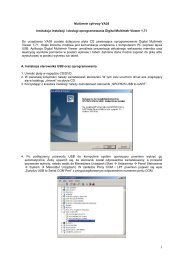
Pic. 2.9: New notification<br />
Notification via SMS - installation and configuration<br />
of GSM-modem<br />
The monitoring system can send notifications via SMS after you have installed and configured<br />
GSM modem. To configure the GSM modem, follow these steps:<br />
1. Disconnect system power cable from the mains supply.<br />
2. Open the metal case of the system by unscrewing the bolts and removing the<br />
cover.<br />
3. Connect the SIM-card to the modem.<br />
4. Connect modem to the system by two M3 bolts, connect one end of the cable<br />
to port on modem board and the other to the port on the system board.