Buffer Insertion Basics - Computer Engineering & Systems Group ...
Buffer Insertion Basics - Computer Engineering & Systems Group ...
Buffer Insertion Basics - Computer Engineering & Systems Group ...

You also want an ePaper? Increase the reach of your titles
YUMPU automatically turns print PDFs into web optimized ePapers that Google loves.
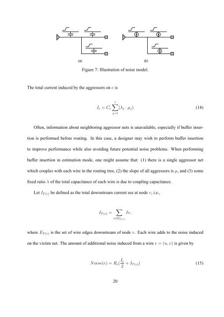
(a)<br />
(b)<br />
Figure 7: Illustration of noise model.<br />
The total current induced by the aggressors on e is<br />
t∑<br />
I e = C e (λ j · µ j ) (14)<br />
j=1<br />
Often, information about neighboring aggressor nets is unavailable, especially if buffer insertion<br />
is performed before routing. In this case, a designer may wish to perform buffer insertion<br />
to improve performance while also avoiding future potential noise problems. When performing<br />
buffer insertion in estimation mode, one might assume that: (1) there is a single aggressor net<br />
which couples with each wire in the routing tree, (2) the slope of all aggressors is µ, and (3) some<br />
fixed ratio λ of the total capacitance of each wire is due to coupling capacitance.<br />
Let I T(v) be defined as the total downstream current see at node v, i.e.,<br />
I T(v) = ∑<br />
e∈E T(v)<br />
Ie,<br />
where E T(v) is the set of wire edges downstream of node v. Each wire adds to the noise induced<br />
on the victim net. The amount of additional noise induced from a wire e = (u,v) is given by<br />
Noise(e) = R e ( I e<br />
2 + I T(v)) (15)<br />
20