Buffer Insertion Basics - Computer Engineering & Systems Group ...
Buffer Insertion Basics - Computer Engineering & Systems Group ...
Buffer Insertion Basics - Computer Engineering & Systems Group ...

Create successful ePaper yourself
Turn your PDF publications into a flip-book with our unique Google optimized e-Paper software.
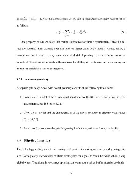
and m (0)<br />
AB = m(0) AD<br />
= 1. Now the moments from A to C can be computed via moment multiplication<br />
as follows.<br />
m (i)<br />
AC = i∑<br />
(m (j)<br />
AB · m(i−j)<br />
j=0<br />
BC ) (24)<br />
One property of Elmore delay that makes it attractive for timing optimization is that the delays<br />
are additive. This property does not hold for higher order delay models. Consequently, a<br />
non-critical sink in a subtree may become a critical sink depending the value of upstream resistance<br />
[35]. Therefore, one must store the moments for all the paths to downstream sinks during the<br />
bottom-up candidate solution propagation.<br />
4.7.3 Accurate gate delay<br />
A popular gate delay model with decent accuracy consists of the following three steps:<br />
1. Compute a π−model of the driving point admittance for the RC interconnect using the techniques<br />
introduced in Section 4.7.1.<br />
2. Given the π−model and the characteristics of the driver, compute an effective capacitance<br />
C eff [31, 32].<br />
3. Based on C eff , compute the gate delay using k−factor equations or lookup table [36].<br />
4.8 Flip-flop <strong>Insertion</strong><br />
The technology scaling leads to decreasing clock period, increasing wire delay and growing chip<br />
size. Consequently, it often takes multiple clock cycles for signals to reach their destinations along<br />
global wires. Traditional interconnect optimization techniques such as buffer insertion are inade-<br />
27