Buffer Insertion Basics - Computer Engineering & Systems Group ...
Buffer Insertion Basics - Computer Engineering & Systems Group ...
Buffer Insertion Basics - Computer Engineering & Systems Group ...

You also want an ePaper? Increase the reach of your titles
YUMPU automatically turns print PDFs into web optimized ePapers that Google loves.
4.7 Higher Order Delay Modeling<br />
Many buffer insertion methods [11, 12, 28] are based on the Elmore wire delay model [29] and<br />
a linear gate delay model for the sake of simplicity. However, the Elmore delay model often<br />
overestimates interconnect delay. It is observed in [30] that Elmore delay sometimes has over<br />
100% overestimation error when compared to SPICE. A critical reason of the overestimation is<br />
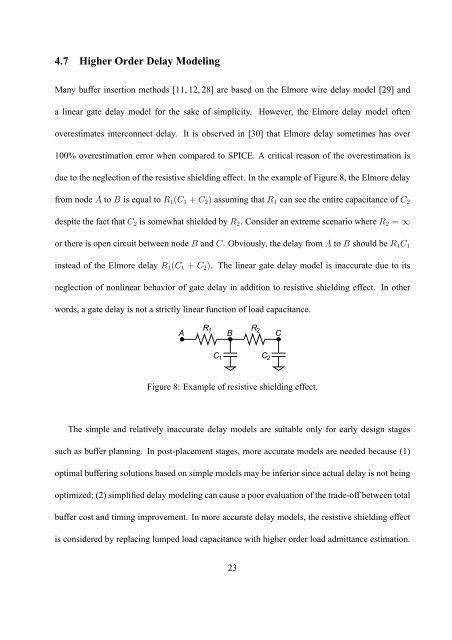
due to the neglection of the resistive shielding effect. In the example of Figure 8, the Elmore delay<br />
from node A to B is equal to R 1 (C 1 + C 2 ) assuming that R 1 can see the entire capacitance of C 2<br />
despite the fact that C 2 is somewhat shielded by R 2 . Consider an extreme scenario where R 2 = ∞<br />
or there is open circuit between node B and C. Obviously, the delay from A to B should be R 1 C 1<br />
instead of the Elmore delay R 1 (C 1 + C 2 ). The linear gate delay model is inaccurate due to its<br />
neglection of nonlinear behavior of gate delay in addition to resistive shielding effect. In other<br />
words, a gate delay is not a strictly linear function of load capacitance.<br />
A<br />
R 1 R 2<br />
C 2<br />
C 1<br />
B C<br />
Figure 8: Example of resistive shielding effect.<br />
The simple and relatively inaccurate delay models are suitable only for early design stages<br />
such as buffer planning. In post-placement stages, more accurate models are needed because (1)<br />
optimal buffering solutions based on simple models may be inferior since actual delay is not being<br />
optimized; (2) simplified delay modeling can cause a poor evaluation of the trade-off between total<br />
buffer cost and timing improvement. In more accurate delay models, the resistive shielding effect<br />
is considered by replacing lumped load capacitance with higher order load admittance estimation.<br />
23