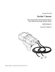
DOC023.53.80040 sc200 Controller - Hachflow
DOC023.53.80040 sc200 Controller - Hachflow
DOC023.53.80040 sc200 Controller - Hachflow

Create successful ePaper yourself
Turn your PDF publications into a flip-book with our unique Google optimized e-Paper software.
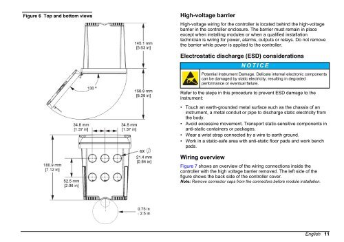
Figure 6 Top and bottom views<br />
High-voltage barrier<br />
High-voltage wiring for the controller is located behind the high-voltage<br />
barrier in the controller enclosure. The barrier must remain in place<br />
except when installing modules or when a qualified installation<br />
technician is wiring for power, alarms, outputs or relays. Do not remove<br />
the barrier while power is applied to the controller.<br />
Electrostatic discharge (ESD) considerations<br />
N O T I C E<br />
Potential Instrument Damage. Delicate internal electronic components<br />
can be damaged by static electricity, resulting in degraded<br />
performance or eventual failure.<br />
Refer to the steps in this procedure to prevent ESD damage to the<br />
instrument:<br />
• Touch an earth-grounded metal surface such as the chassis of an<br />
instrument, a metal conduit or pipe to discharge static electricity from<br />
the body.<br />
• Avoid excessive movement. Transport static-sensitive components in<br />
anti-static containers or packages.<br />
• Wear a wrist strap connected by a wire to earth ground.<br />
• Work in a static-safe area with anti-static floor pads and work bench<br />
pads.<br />
Wiring overview<br />
Figure 7 shows an overview of the wiring connections inside the<br />
controller with the high voltage barrier removed. The left side of the<br />
figure shows the back side of the controller cover.<br />
Note: Remove connector caps from the connectors before module installation.<br />
English 11