DOC023.53.80040 sc200 Controller - Hachflow
DOC023.53.80040 sc200 Controller - Hachflow
DOC023.53.80040 sc200 Controller - Hachflow

You also want an ePaper? Increase the reach of your titles
YUMPU automatically turns print PDFs into web optimized ePapers that Google loves.
1. The equipment may not cause harmful interference.<br />
2. The equipment must accept any interference received, including<br />
interference that may cause undesired operation.<br />
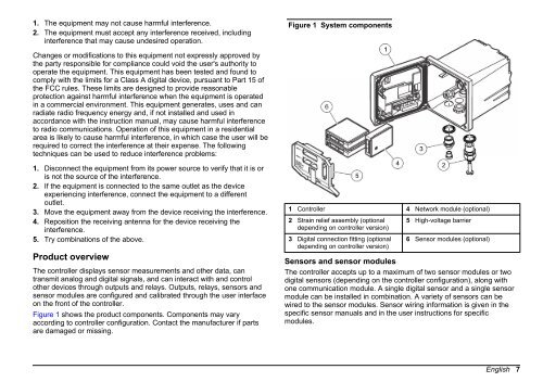
Figure 1 System components<br />
Changes or modifications to this equipment not expressly approved by<br />
the party responsible for compliance could void the user's authority to<br />
operate the equipment. This equipment has been tested and found to<br />
comply with the limits for a Class A digital device, pursuant to Part 15 of<br />
the FCC rules. These limits are designed to provide reasonable<br />
protection against harmful interference when the equipment is operated<br />
in a commercial environment. This equipment generates, uses and can<br />
radiate radio frequency energy and, if not installed and used in<br />
accordance with the instruction manual, may cause harmful interference<br />
to radio communications. Operation of this equipment in a residential<br />
area is likely to cause harmful interference, in which case the user will be<br />
required to correct the interference at their expense. The following<br />
techniques can be used to reduce interference problems:<br />
1. Disconnect the equipment from its power source to verify that it is or<br />
is not the source of the interference.<br />
2. If the equipment is connected to the same outlet as the device<br />
experiencing interference, connect the equipment to a different<br />
outlet.<br />
3. Move the equipment away from the device receiving the interference.<br />
4. Reposition the receiving antenna for the device receiving the<br />
interference.<br />
5. Try combinations of the above.<br />
Product overview<br />
The controller displays sensor measurements and other data, can<br />
transmit analog and digital signals, and can interact with and control<br />
other devices through outputs and relays. Outputs, relays, sensors and<br />
sensor modules are configured and calibrated through the user interface<br />
on the front of the controller.<br />
Figure 1 shows the product components. Components may vary<br />
according to controller configuration. Contact the manufacturer if parts<br />
are damaged or missing.<br />
1 <strong>Controller</strong> 4 Network module (optional)<br />
2 Strain relief assembly (optional<br />
depending on controller version)<br />
3 Digital connection fitting (optional<br />
depending on controller version)<br />
5 High-voltage barrier<br />
6 Sensor modules (optional)<br />
Sensors and sensor modules<br />
The controller accepts up to a maximum of two sensor modules or two<br />
digital sensors (depending on the controller configuration), along with<br />
one communication module. A single digital sensor and a single sensor<br />
module can be installed in combination. A variety of sensors can be<br />
wired to the sensor modules. Sensor wiring information is given in the<br />
specific sensor manuals and in the user instructions for specific<br />
modules.<br />
English 7