Open Core Protocol Debug Interface Specification rev 1.0 - OCP-IP
Open Core Protocol Debug Interface Specification rev 1.0 - OCP-IP
Open Core Protocol Debug Interface Specification rev 1.0 - OCP-IP

You also want an ePaper? Increase the reach of your titles
YUMPU automatically turns print PDFs into web optimized ePapers that Google loves.
<strong>OCP</strong>-<strong>IP</strong> Confidential<br />
tracing is active. If this one clock can be synchronous to or multiple of all local clocks then this<br />
concept is great. Otherwise, this concept requires fair amount of over clocking to resolve even<br />
smallest possible phase relationships between the asynchronous clocks.<br />
Stamp clock and stamp reset signals are both part of the basic <strong>OCP</strong> debug interface and<br />
designers must decide which one shall be base for the global debug synchrony.<br />
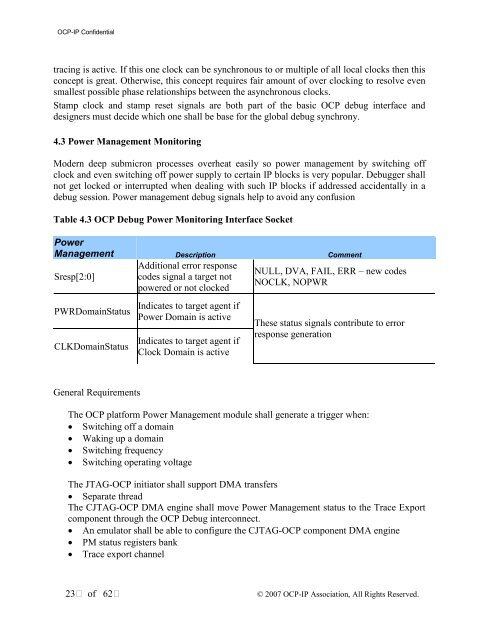
4.3 Power Management Monitoring<br />
Modern deep submicron processes overheat easily so power management by switching off<br />
clock and even switching off power supply to certain <strong>IP</strong> blocks is very popular. <strong>Debug</strong>ger shall<br />
not get locked or interrupted when dealing with such <strong>IP</strong> blocks if addressed accidentally in a<br />
debug session. Power management debug signals help to avoid any confusion<br />
Table 4.3 <strong>OCP</strong> <strong>Debug</strong> Power Monitoring <strong>Interface</strong> Socket<br />
Power<br />
Management Description Comment<br />
Sresp[2:0]<br />
PWRDomainStatus<br />
CLKDomainStatus<br />
Additional error response<br />
codes signal a target not<br />
powered or not clocked<br />
Indicates to target agent if<br />
Power Domain is active<br />
Indicates to target agent if<br />
Clock Domain is active<br />
NULL, DVA, FAIL, ERR – new codes<br />
NOCLK, NOPWR<br />
These status signals contribute to error<br />
response generation<br />
General Requirements<br />
The <strong>OCP</strong> platform Power Management module shall generate a trigger when:<br />
• Switching off a domain<br />
• Waking up a domain<br />
• Switching frequency<br />
• Switching operating voltage<br />
The JTAG-<strong>OCP</strong> initiator shall support DMA transfers<br />
• Separate thread<br />
The CJTAG-<strong>OCP</strong> DMA engine shall move Power Management status to the Trace Export<br />
component through the <strong>OCP</strong> <strong>Debug</strong> interconnect.<br />
• An emulator shall be able to configure the CJTAG-<strong>OCP</strong> component DMA engine<br />
• PM status registers bank<br />
• Trace export channel<br />
23 of 62<br />
© 2007 <strong>OCP</strong>-<strong>IP</strong> Association, All Rights Reserved.