Open Core Protocol Debug Interface Specification rev 1.0 - OCP-IP
Open Core Protocol Debug Interface Specification rev 1.0 - OCP-IP
Open Core Protocol Debug Interface Specification rev 1.0 - OCP-IP

You also want an ePaper? Increase the reach of your titles
YUMPU automatically turns print PDFs into web optimized ePapers that Google loves.
<strong>OCP</strong>-<strong>IP</strong> Confidential<br />
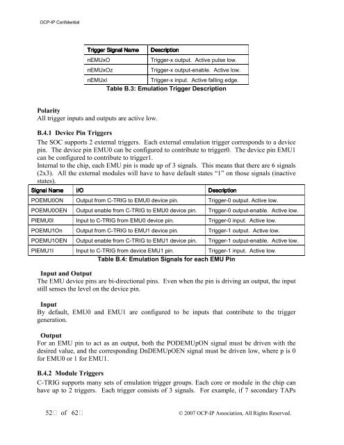
Trigger Signal Name<br />
nEMUxO<br />
nEMUxOz<br />
Description<br />
Trigger-x output. Active pulse low.<br />
Trigger-x output-enable. Active low.<br />
nEMUxI<br />
Trigger-x input. Active falling edge.<br />
Table B.3: Emulation Trigger Description<br />
Polarity<br />
All trigger inputs and outputs are active low.<br />
B.4.1 Device Pin Triggers<br />
The SOC supports 2 external triggers. Each external emulation trigger corresponds to a device<br />
pin. The device pin EMU0 can be configured to contribute to trigger0. The device pin EMU1<br />
can be configured to contribute to trigger1.<br />
Internal to the chip, each EMU pin is made up of 3 signals. This means that there are 6 signals<br />
(2x3). All the external modules will have to have default states “1” on those signals (inactive<br />
states).<br />
Signal Name<br />
I/O<br />
Description<br />
POEMU0ON Output from C-TRIG to EMU0 device pin. Trigger-0 output. Active low.<br />
POEMU0OEN Output enable from C-TRIG to EMU0 device pin. Trigger-0 output-enable. Active low.<br />
PIEMU0I Input to C-TRIG from EMU0 device pin. Trigger-0 input. Active low.<br />
POEMU1On Output from C-TRIG to EMU1 device pin. Trigger-1 output. Active low.<br />
POEMU1OEN Output enable from C-TRIG to EMU1 device pin. Trigger-1 output-enable. Active low.<br />
PIEMU1I Input to C-TRIG from device EMU1 pin. Trigger-1 input. Active low.<br />
Table B.4: Emulation Signals for each EMU Pin<br />
Input and Output<br />
The EMU device pins are bi-directional pins. Even when the pin is driving an output, the input<br />
still senses the level on the device pin.<br />
Input<br />
By default, EMU0 and EMU1 are configured to be inputs that contribute to the trigger<br />
generation.<br />
Output<br />
For an EMU pin to act as an output, both the PODEMUpON signal must be driven with the<br />
desired value, and the corresponding DnDEMUpOEN signal must be driven low, where p is 0<br />
for EMU0 or 1 for EMU1.<br />
B.4.2 Module Triggers<br />
C-TRIG supports many sets of emulation trigger groups. Each core or module in the chip can<br />
have up to 2 triggers. Each trigger consists of 3 signals. For example, if 7 secondary TAPs<br />
52 of 62<br />
© 2007 <strong>OCP</strong>-<strong>IP</strong> Association, All Rights Reserved.