Open Core Protocol Debug Interface Specification rev 1.0 - OCP-IP
Open Core Protocol Debug Interface Specification rev 1.0 - OCP-IP
Open Core Protocol Debug Interface Specification rev 1.0 - OCP-IP

You also want an ePaper? Increase the reach of your titles
YUMPU automatically turns print PDFs into web optimized ePapers that Google loves.
<strong>OCP</strong>-<strong>IP</strong> Confidential<br />
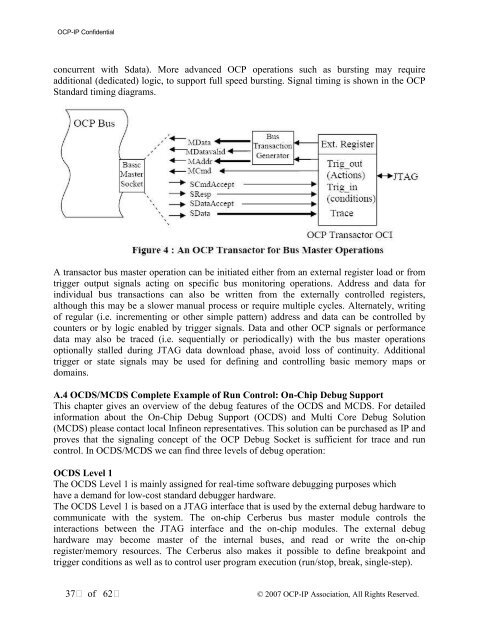
concurrent with Sdata). More advanced <strong>OCP</strong> operations such as bursting may require<br />
additional (dedicated) logic, to support full speed bursting. Signal timing is shown in the <strong>OCP</strong><br />
Standard timing diagrams.<br />
A transactor bus master operation can be initiated either from an external register load or from<br />
trigger output signals acting on specific bus monitoring operations. Address and data for<br />
individual bus transactions can also be written from the externally controlled registers,<br />
although this may be a slower manual process or require multiple cycles. Alternately, writing<br />
of regular (i.e. incrementing or other simple pattern) address and data can be controlled by<br />
counters or by logic enabled by trigger signals. Data and other <strong>OCP</strong> signals or performance<br />
data may also be traced (i.e. sequentially or periodically) with the bus master operations<br />
optionally stalled during JTAG data download phase, avoid loss of continuity. Additional<br />
trigger or state signals may be used for defining and controlling basic memory maps or<br />
domains.<br />
A.4 OCDS/MCDS Complete Example of Run Control: On-Chip <strong>Debug</strong> Support<br />
This chapter gives an overview of the debug features of the OCDS and MCDS. For detailed<br />
information about the On-Chip <strong>Debug</strong> Support (OCDS) and Multi <strong>Core</strong> <strong>Debug</strong> Solution<br />
(MCDS) please contact local Infineon representatives. This solution can be purchased as <strong>IP</strong> and<br />
proves that the signaling concept of the <strong>OCP</strong> <strong>Debug</strong> Socket is sufficient for trace and run<br />
control. In OCDS/MCDS we can find three levels of debug operation:<br />
OCDS Level 1<br />
The OCDS Level 1 is mainly assigned for real-time software debugging purposes which<br />
have a demand for low-cost standard debugger hardware.<br />
The OCDS Level 1 is based on a JTAG interface that is used by the external debug hardware to<br />
communicate with the system. The on-chip Cerberus bus master module controls the<br />
interactions between the JTAG interface and the on-chip modules. The external debug<br />
hardware may become master of the internal buses, and read or write the on-chip<br />
register/memory resources. The Cerberus also makes it possible to define breakpoint and<br />
trigger conditions as well as to control user program execution (run/stop, break, single-step).<br />
37 of 62<br />
© 2007 <strong>OCP</strong>-<strong>IP</strong> Association, All Rights Reserved.