Open Core Protocol Debug Interface Specification rev 1.0 - OCP-IP
Open Core Protocol Debug Interface Specification rev 1.0 - OCP-IP
Open Core Protocol Debug Interface Specification rev 1.0 - OCP-IP
You also want an ePaper? Increase the reach of your titles
YUMPU automatically turns print PDFs into web optimized ePapers that Google loves.
<strong>OCP</strong>-<strong>IP</strong> Confidential<br />
If EMU1 is driven LOW it will result in the generation of GNEMUINT1, which will in turn<br />
generate the IC_EMUINTR.<br />
IC_EMUINTR is an input of the CPU interrupt controller.<br />
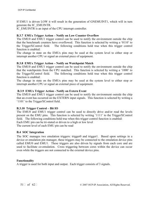
B.3.7 EMUx Trigger Action – Notify on Low Counter Overflow<br />
The EMU0 and EMU1 trigger control can be used to notify the environment outside the chip<br />
that the benchmark counters have overflowed. This function is selected by writing a ‘0110’ to<br />
the TriggerXControl field. The following conditions hold true when this trigger control<br />
function is enabled:<br />
The change in state on the EMUx pins may be used at the system level to either stop or<br />
interrupt another CPU or signal an external piece of equipment.<br />
B.3.8 EMUx Trigger Action – Notify on Watchpoint Match<br />
The EMU0 and EMU1 trigger control can be used to notify the environment outside the chip<br />
that the watchpoints from the CPU matched. This function is selected by writing a ‘1000’ to<br />
the TriggerXControl field. The following conditions hold true when this trigger control<br />
function is enabled:<br />
The change in state on the EMUx pins may be used at the system level to either stop or<br />
interrupt another CPU or signal an external piece of equipment.<br />
B.3.9 EMUx Trigger Action - Notify on Extern Event<br />
The EMU0 and EMU1 trigger control can be used to notify the environment outside the chip<br />
that an event has occurred on the EXTERN input signals. This function is selected by writing a<br />
‘1101’ to the TriggerXControl field.<br />
B.3.10 Trigger Control – Bit IO<br />
The EMU0 and EMU1 trigger control can be used to directly drive and/or read the levels<br />
present on the EMU pins. This function is selected by writing ‘1111’ to the TriggerXControl<br />
field. The following conditions hold true when this trigger control function is enabled:<br />
Each EMU pin can be tri-stated or driven to a high or low level<br />
The current level of each EMU pin can be read<br />
B.4 SOC Integration<br />
The SOC manages two emulation triggers: trigger0 and trigger1. Based upon settings in a<br />
device or emulation pin manager, these triggers may be connected to the emulation device pins<br />
called EMU0 and EMU1. These triggers are also driven by signals from each core and are<br />
used to facilitate co-emulation. Cross triggering between cores within the device can occur<br />
even while the triggers are not connected to the external device pins.<br />
Functionality<br />
A trigger is used for both input and output. Each trigger consists of 3 signals.<br />
51 of 62<br />
© 2007 <strong>OCP</strong>-<strong>IP</strong> Association, All Rights Reserved.


