Engine Titanium Consortium - Center for Nondestructive Evaluation ...
Engine Titanium Consortium - Center for Nondestructive Evaluation ...
Engine Titanium Consortium - Center for Nondestructive Evaluation ...

You also want an ePaper? Increase the reach of your titles
YUMPU automatically turns print PDFs into web optimized ePapers that Google loves.
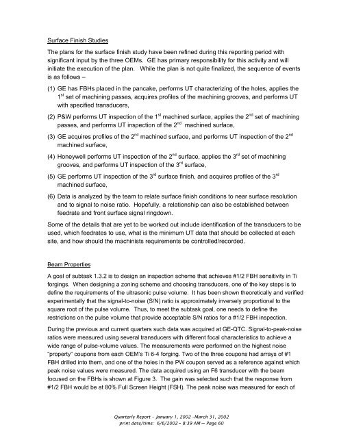
Surface Finish Studies<br />
The plans <strong>for</strong> the surface finish study have been refined during this reporting period with<br />
significant input by the three OEMs. GE has primary responsibility <strong>for</strong> this activity and will<br />
initiate the execution of the plan. While the plan is not quite finalized, the sequence of events<br />
is as follows –<br />
(1) GE has FBHs placed in the pancake, per<strong>for</strong>ms UT characterizing of the holes, applies the<br />
1 st set of machining passes, acquires profiles of the machining grooves, and per<strong>for</strong>ms UT<br />
with specified transducers,<br />
(2) P&W per<strong>for</strong>ms UT inspection of the 1 st machined surface, applies the 2 nd set of machining<br />
passes, and per<strong>for</strong>ms UT inspection of the 2 nd machined surface,<br />
(3) GE acquires profiles of the 2 nd machined surface, and per<strong>for</strong>ms UT inspection of the 2 nd<br />
machined surface,<br />
(4) Honeywell per<strong>for</strong>ms UT inspection of the 2 nd surface, applies the 3 rd set of machining<br />
grooves, and per<strong>for</strong>ms UT inspection of the 3 rd surface,<br />
(5) GE per<strong>for</strong>ms UT inspection of the 3 rd surface finish, and acquires profiles of the 3 rd<br />
machined surface,<br />
(6) Data is analyzed by the team to relate surface finish conditions to near surface resolution<br />
and to signal to noise ratio. Hopefully, a relationship can also be established between<br />
feedrate and front surface signal ringdown.<br />
Some of the details that are yet to be worked out include identification of the transducers to be<br />
used, which feedrates to use, what is the minimum UT data that should be collected at each<br />
site, and how should the machinists requirements be controlled/recorded.<br />
Beam Properties<br />
A goal of subtask 1.3.2 is to design an inspection scheme that achieves #1/2 FBH sensitivity in Ti<br />
<strong>for</strong>gings. When designing a zoning scheme and choosing transducers, one of the key steps is to<br />
define the requirements of the ultrasonic pulse volume. It has been shown theoretically and verified<br />
experimentally that the signal-to-noise (S/N) ratio is approximately inversely proportional to the<br />
square root of the pulse volume. Thus, to meet the subtask goal, one needs to define the<br />
restrictions on the pulse volume that provide acceptable S/N ratios <strong>for</strong> a #1/2 FBH inspection.<br />
During the previous and current quarters such data was acquired at GE-QTC. Signal-to-peak-noise<br />
ratios were measured using several transducers with different focal characteristics to achieve a<br />
wide range of pulse-volume values. The measurements were per<strong>for</strong>med on the highest noise<br />
“property” coupons from each OEM’s Ti 6-4 <strong>for</strong>ging. Two of the three coupons had arrays of #1<br />
FBH drilled into them, and one of the holes in the PW coupon served as a reference against which<br />
peak noise values were measured. The data acquired using an F6 transducer with the beam<br />
focused on the FBHs is shown at Figure 3. The gain was selected such that the response from<br />
#1/2 FBH would be at 80% Full Screen Height (FSH). The peak noise was measured <strong>for</strong> each of<br />
Quarterly Report – January 1, 2002 –March 31, 2002<br />
print date/time: 6/6/2002 - 8:39 AM – Page 60