2 - Schneider Electric CZ, s.r.o.
2 - Schneider Electric CZ, s.r.o.
2 - Schneider Electric CZ, s.r.o.

Create successful ePaper yourself
Turn your PDF publications into a flip-book with our unique Google optimized e-Paper software.
Presentation<br />
Machine safety<br />
Functional Safety of Machinery<br />
Introduction<br />
Standard EN ISO 13849-1<br />
1<br />
2<br />
3<br />
4<br />
5<br />
6<br />
7<br />
8<br />
9<br />
10<br />
Event: limit switch<br />
Standards to be applied according to<br />
the design selected for the safetyrelated<br />
machine control system<br />
Guard<br />
contact<br />
Safety functions<br />
Logic<br />
Representation of the safety function<br />
L<br />
Contactor<br />
Inputs Processing Outputs<br />
Risk related<br />
to the<br />
potential<br />
hazard<br />
Risk analysis<br />
Severity .<br />
of the potential<br />
harm<br />
Action: motor stop<br />
Probability of<br />
occurrence: .<br />
- Frequency and<br />
duration of<br />
exposure<br />
- Possibility of<br />
avoiding or<br />
limiting the<br />
probability of the<br />
occurrence of an<br />
event that could<br />
cause the harm<br />
Introduction to Functional Safety of Machinery<br />
The functional safety standards are intended to encourage designers to<br />
focus more on the functions that are necessary to reduce each individual<br />
risk, and on the performance required for each function, rather than simply<br />
relying on particular components. These standards make it possible to<br />
achieve greater levels of safety throughout the machine’s life.<br />
> > Under the old standard, EN 954-1, categories (B, 1, 2, 3 and 4) dictated how a<br />
safety-related electrical control circuit must behave under fault conditions.<br />
Designers can follow either EN ISO 13849-1 or EN/IEC 62061 to demonstrate<br />
conformity with the Machinery Directive. These two new standards consider not<br />
only whether a fault will occur, but also how likely it is to occur.<br />
> > This means there is a quantifiable, probabilistic element in compliance: machine<br />
builders must be able to determine whether their safety circuit meets the<br />
required safety integrity level (SIL) or performance level (PL). Panel builders and<br />
designers should be aware that manufacturers of the components used in safety<br />
circuits (such as safety detection components, safety logic solvers and output<br />
devices like contactors) must provide detailed data on their products.<br />
Standard EN ISO 13849-1<br />
Machinery safety - Safety-related parts of control systems<br />
Standard EN ISO 13849-1 is an evolution of standard EN 954-1.<br />
Field of application of the standard<br />
This standard gives safety requirements and advice relating to principles for the<br />
design and integration of safety-related parts of control systems (SRP/CS),<br />
including software design. For these parts, it specifies the characteristics, including<br />
the performance level, needed to achieve these safety functions. It applies to the<br />
SRP/CS of all types of machine, regardless of the technology and type of energy<br />
used (electric, hydraulic, pneumatic, mechanical, etc.).<br />
Process<br />
Risk assessment as defined in standard EN/ISO 12100 leads to decisions on risk<br />
reduction measures.<br />
If these measures depend on a control system, then EN/ISO 12100 can apply..It defines<br />
a 6-stage design process:<br />
1 - Selection of the essential safety functions that SRP/CS must perform. For each<br />
safety function, specify the required characteristics<br />
2 - Determine the required performance level (PLr)<br />
3 - Design and technical creation of safety functions: identify the parts that perform<br />
the safety function<br />
4 - Evaluate the performance level PL for each safety-related part<br />
5 - Check that the performance level PL achieved is greater than or equal to the<br />
required level (PLr)<br />
6 - Check that all requirements are satisfied<br />
We will now illustrate these stages, taking as an example a safety function where a<br />
severe injury can be caused by a trolley not stopping at the end of the Jib and thus<br />
causing the trolley to fall. A person can be exposed to this dangerous situation<br />
around the hoisting machine.<br />
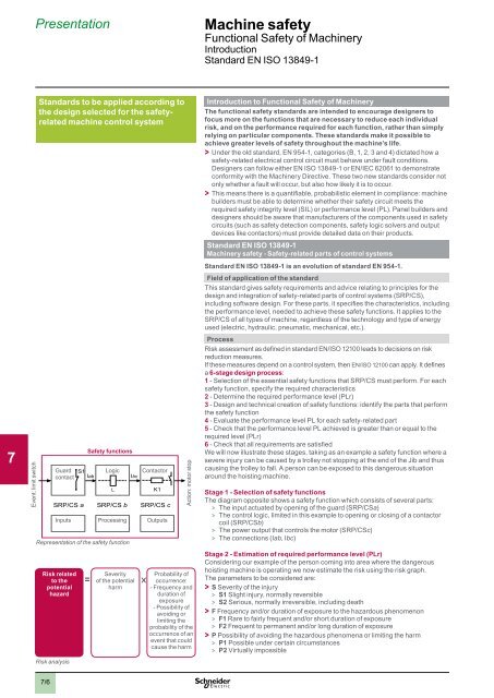
Stage 1 - Selection of safety functions<br />
The diagram opposite shows a safety function which consists of several parts:<br />
> > The input actuated by opening of the guard (SRP/CSa)<br />
> > The control logic, limited in this example to opening or closing of a contactor<br />
coil (SRP/CSb)<br />
> > The power output that controls the motor (SRP/CSc)<br />
> > The connections (Iab, Ibc)<br />
Stage 2 - Estimation of required performance level (PLr)<br />
Considering our example of the person coming into area where the dangerous<br />
hoisting machine is operating we now estimate the risk using the risk graph.<br />
The parameters to be considered are:<br />
> > S Severity of the injury<br />
> > S1 Slight injury, normally reversible<br />
> > S2 Serious, normally irreversible, including death<br />
> > F Frequency and/or duration of exposure to the hazardous phenomenon<br />
> > F1 Rare to fairly frequent and/or short duration of exposure<br />
> > F2 Frequent to permanent and/or long duration of exposure<br />
> > P Possibility of avoiding the hazardous phenomena or limiting the harm<br />
> > P1 Possible under certain circumstances<br />
> > P2 Virtually impossible<br />
7/6