2 - Schneider Electric CZ, s.r.o.
2 - Schneider Electric CZ, s.r.o.
2 - Schneider Electric CZ, s.r.o.

Create successful ePaper yourself
Turn your PDF publications into a flip-book with our unique Google optimized e-Paper software.
Description<br />
Controllers<br />
Modicon M238 logic controller<br />
Compact base for solutions with AFB<br />
1<br />
2<br />
3<br />
4<br />
5<br />
1 2 3 4 5<br />
10 9 8<br />
6<br />
7<br />
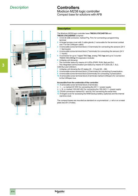
Description<br />
The Modicon M238 logic controller base TM238 LFDC24DTS0 and<br />
TM238 LFAC24DRS0 comprise:<br />
1 A mini B USB connector, marked Prg. Port, for connecting a programming<br />
terminal<br />
2 A hinged access cover with 2 cable glands (1 removable for the terminal cordset<br />
and 1 for the CANopen cable)<br />
3 A removable screw terminal block (12 terminals) for connecting the sensors (24 V<br />
c fast inputs)<br />
4 A removable screw terminal block (7 terminals) for connecting the sensors (24 V<br />
c inputs)<br />
5 A connector for up to 7 digital TM2 Dpp, analog TM2 App and up to 3 counter<br />
TM200 HSC206Dp I/O expansion modules<br />
6 A display unit showing:<br />
--<br />
The controller status by means of 4 LEDs (PWR, RUN, Batt and Err)<br />
--<br />
The integrated communication port status by means of 4 LEDs (SL1, SL2,<br />
CAN Run and CAN Err)<br />
7 A display unit showing the I/O states (I0…I13 and Q0…Q9)<br />
8 A removable screw terminal block (10 terminals) for connecting 6 preactuators<br />
9 A removable screw terminal block (6 terminals) for connecting 4 preactuators<br />
10 A removable screw terminal block (5 terminals marked CANopen) for connection<br />
to the CANopen bus.<br />
Accessible from the underside of the controller:<br />
11 A removable screw terminal block (3 terminals):<br />
v v +, -, t marked 24 VDC for connecting the 24 V c power supply<br />
vv<br />
L, N, t marked 100-240 VAC for connecting the 100-240 V a power supply<br />
12 2 RJ45 connectors marked SL1 and SL2 for connecting the serial links<br />
13 A hinged cover for accessing the RAM backup battery (optional) and the internal<br />
real-time clock<br />
The compact bases are mounted as standard on a symmetrical 5 rail or on a metal<br />
plate (two Ø 4.3 holes).<br />
6<br />
11 12 13<br />
7<br />
8<br />
9<br />
10<br />
3/14