2 - Schneider Electric CZ, s.r.o.
2 - Schneider Electric CZ, s.r.o.
2 - Schneider Electric CZ, s.r.o.

You also want an ePaper? Increase the reach of your titles
YUMPU automatically turns print PDFs into web optimized ePapers that Google loves.
Presentation<br />
Machine safety<br />
Functional Safety of Machinery<br />
Standard EN ISO 13849-1<br />
Standard EN ISO 13849-1<br />
Machinery safety - Safety-related parts of control systems<br />
Process (continued)<br />
Stage 4 - Evaluate the performance level PL for each safety-related part<br />
Typically the data needed for the calculation of the performance level is being<br />
provided by the components supplier. For safety processing devices the MTTF d<br />
,<br />
DC and performance level values are provided. For other non-safety components<br />
such as contactors, limit switches, etc. which wear primary as a result of their<br />
mechanical actuation, B10 d<br />
values are provided by the supplier in some cases.<br />
When the B10 d<br />
values are not available, the annex C from the 13849-1 standard<br />
has to be used.<br />
Example<br />
B 10d<br />
(where 10% of the population fail MTTF d<br />
DC<br />
to dangerous failure mode)<br />
SRP/CS a<br />
: Limit switch<br />
2 000 000 (the B10 d<br />
is coming from the 284 –<br />
typical components values table from<br />
Annex C 13849-1)<br />
SRP/CS b<br />
: XPS AXE safety module - 457 99,99%<br />
SRP/CS c<br />
: TeSys contactor 1 369 863 194 99%<br />
> > For estimating the performance level of a safety function, the condition is that the<br />
MTTF d<br />
, the DC and the category from each component are known. The<br />
procedure to follow:<br />
> > Calculation of MTTF d<br />
and DC of the complete system<br />
> > Analysis of the category.<br />
> > For electromechanical products, the MTTF d<br />
is calculated on the basis of the total<br />
number of operations that the product can perform, using B 10d<br />
values:<br />
In our case, the machine operates for 220 days per year, 8 hours per day with a<br />
cycle of 90 s<br />
N = 220 x 8 x (3600 / 90) = 70 400 operations/year<br />
MTTF d<br />
= B 10d<br />
/ (0.1 x N)<br />
> > For the limit switch: the MTTF d<br />
= (2 000 000) / (0.1) x 70 400 = 284 years<br />
> > For the contactor:<br />
> > The MTTF d<br />
= (1 369 863) / (0.1) x 70 400 = 194 years<br />
The MTTF d<br />
for each channel will then be calculated using the formula:<br />
i.e. 284 years.<br />
A similar formula is used to calculate the diagnostic capability<br />
1<br />
2<br />
3<br />
4<br />
5<br />
6<br />
The DC is our example is < 60%, e.g. nil.<br />
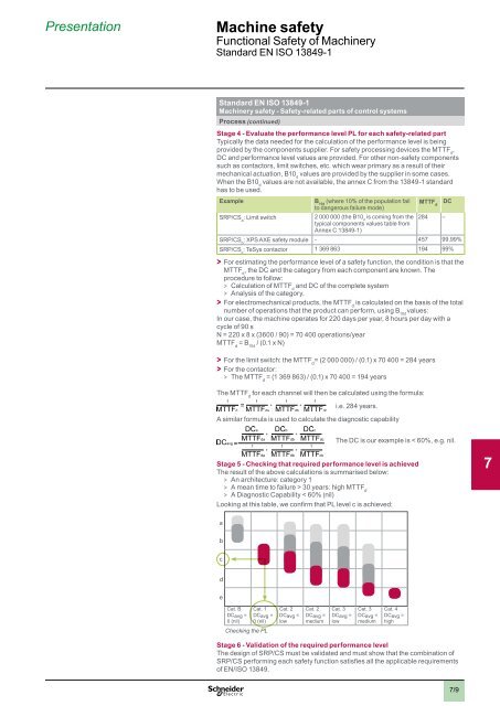
Stage 5 - Checking that required performance level is achieved<br />
The result of the above calculations is summarised below:<br />
> > An architecture: category 1<br />
> > A mean time to failure > 30 years: high MTTF d<br />
> > A Diagnostic Capability < 60% (nil)<br />
Looking at this table, we confirm that PL level c is achieved:<br />
a<br />
7<br />
8<br />
b<br />
c<br />
d<br />
9<br />
e<br />
Cat. B Cat. 1 Cat. 2 Cat. 2 Cat. 3 Cat. 3 Cat. 4<br />
DCavg =<br />
0 (nil)<br />
DCavg =<br />
0 (nil)<br />
DCavg =<br />
low<br />
DCavg =<br />
medium<br />
DCavg =<br />
low<br />
DCavg =<br />
medium<br />
DCavg =<br />
high<br />
Checking the PL<br />
Stage 6 - Validation of the required performance level<br />
The design of SRP/CS must be validated and must show that the combination of<br />
SRP/CS performing each safety function satisfies all the applicable requirements<br />
of EN/ISO 13849.<br />
10<br />
7/9