2 - Schneider Electric CZ, s.r.o.
2 - Schneider Electric CZ, s.r.o.
2 - Schneider Electric CZ, s.r.o.

Create successful ePaper yourself
Turn your PDF publications into a flip-book with our unique Google optimized e-Paper software.
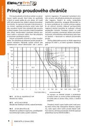
Presentation<br />
Machine safety<br />
Functional Safety of Machinery<br />
Standard EN/IEC 62061<br />
Select the applicable standard<br />
Standard EN/IEC 62061<br />
Machinery safety - Safety-Related <strong>Electric</strong>al Control systems (SRECS)<br />
Process (continued)<br />
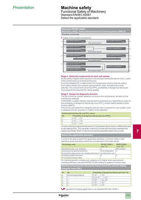
> > Types of sub-system architecture<br />
Sub-system element 1<br />
Sub-system type A<br />
Sub-system element n<br />
1<br />
Sub-system element 1<br />
Sub-system element 2<br />
Sub-system type B<br />
Common cause failure<br />
2<br />
Sub-system element 1<br />
Sub-system element n<br />
Diagnostic function(s)<br />
Sub-system type C<br />
Sub-system element 1<br />
Diagnostic function(s)<br />
Sub-system element 2<br />
Sub-system type D<br />
Common cause failure<br />
3<br />
Stage 4 - Select the components for each sub-system<br />
As the safety integrity level required in the example mentioned above is SIL 2, each<br />
of the components must achieve this level.<br />
Once the targeted SIL is determined, the components constructing the system<br />
from safety-related sub-systems (sensor/switch, logic, actuator) have to be<br />
selected. The components must have PFH d<br />
(probability of dangerous failure per<br />
hour) equal to the required SIL rating needed.<br />
Stage 5 - Design the diagnostic function<br />
The SIL of the sub-system depends not only on the components, but also on the<br />
architecture selected.<br />
In EN 62061, a safety integrity requirement is expressed as a target failure value for<br />
the probability of dangerous failure per hour (PFH d<br />
) of each safety related control<br />
function (SRCF).<br />
This can be calculated from reliability data for each component or sub-system, and<br />
is related to the SIL as shown in Table 3 of the standard:<br />
Relationship between SIL and PFH d<br />
values<br />
SIL Probability of dangerous failures per hour (PFH d<br />
)<br />
3 u 10 -8 ... < 10 -7<br />
2 u 10 -7 ... < 10 -6<br />
1 u 10 -6 ... < 10 -5<br />
For each of the four logical architectures A to D presented above, there is a different formula<br />
to calculate the PFH d<br />
. The calculation method is complex and will not be presented here<br />
(please see EN/IEC 62061 for the formula and the parameters taken into account).<br />
Select the applicable standard<br />
In order to be able to select the applicable standard, a common table in both<br />
standards gives indications which are summarised in the table below:<br />
Technology used EN ISO 13849-1<br />
max. PL<br />
EN/IEC 62061<br />
max. SIL<br />
Non electric only, e.g...hydraulic e Not covered<br />
Including some electromechanical, .<br />
e (for designated 3<br />
for example relays and/or non complex electronics architectures only)<br />
Including complex electronics, .<br />
d 3<br />
for example programmable<br />
For building specific complex sub-systems or for higher level requirements<br />
including software, standard EN/IEC 61508 relating to systems must be used.<br />
Relationship between the performance level (PL) and the Safety<br />
Integrity Level (SIL)<br />
PL SIL Probability of dangerous failures per hour 1/h<br />
a No correspondance u 10 -5 … < 10 -4<br />
b 1 u 3 x 10 -6 … < 10 -5<br />
c 1 u 10 -6 … < 3 x 10 -6<br />
d 2 u 10 -7 … < 10 -6<br />
e 3 u 10 -8 … < 10 -7<br />
4<br />
5<br />
6<br />
7<br />
8<br />
9<br />
10<br />
Typically for hoisting applications use standard EN ISO 13849-1.<br />
7/13