2 - Schneider Electric CZ, s.r.o.
2 - Schneider Electric CZ, s.r.o.
2 - Schneider Electric CZ, s.r.o.

Create successful ePaper yourself
Turn your PDF publications into a flip-book with our unique Google optimized e-Paper software.
Presentation<br />
Machine safety<br />
Functional Safety of Machinery<br />
Standard EN ISO 13849-1<br />
Starting point for the<br />
evaluation of the<br />
contribution to the risk<br />
reduction of a safety<br />
function<br />
Required<br />
performance<br />
level PLr:<br />
Estimation of required performance level<br />
S = Severity of injury<br />
S1 = Slight (normally reversible injury)<br />
S2 = Serious (normally irreversible) injury including death<br />
F = Frequency and/or exposure time to the hazard<br />
F1 = Seldom to less often and/or the exposure time is short<br />
F2 = Frequent to continuous and/or the exposure time is long<br />
P = Possibility of avoiding the hazard or limiting the harm<br />
P1 = Possible under specific conditions<br />
P2 = Scarcely possible<br />
L = Low contribution to risk reduction<br />
H = High contribution to risk reduction<br />
Estimation<br />
L<br />
H<br />
Standard EN ISO 13849-1<br />
Machinery safety - Safety-related parts of control systems<br />
Process (continued)<br />
Stage 2 - Estimation of required performance level (PLr) (continued)<br />
For our example: a serious injury S1 can be caused by being exposed near the hoisting<br />
machine as if there is no safe guarding to ensure the trolley stops the load and trolley will<br />
fall..After considering the severity of the injury we investigate the frequency and/or<br />
duration of the possible entry to the dangerous area..Here we define the frequency of<br />
exposure to the hazard is low F1 (occasional presence) as there are restrictions to enter<br />
the area..The last step is based upon the possibility to avoid the hazard and limiting the<br />
harm..To evaluate this we take into consideration that it is possible to avoid the harm as<br />
the visibility around the dangerous machine is monitored by the operator and in this case<br />
there is a possibility to avoid the harm under certain conditions so we define it as P1.<br />
The result of the estimation gives a required performance level PLr = c.<br />
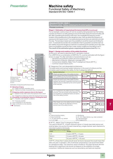
Stage 3 - Design and creation of the safety functions<br />
At this point, we need to describe the PL calculation method.<br />
For a SRP/CS (or a combination of SRP/CS), PL could be estimated with the figure<br />
shown on page 7/9, after estimation of several factors such as :<br />
> > Hardware and software system structure (categories)<br />
> > Mechanism of failures, diagnostic coverage (DC),<br />
> > Components reliability, Mean Time To dangerous Failure (MTTF d<br />
)<br />
> > Common Cause Failure (CCF)<br />
> > Categories (Cat.) and designated architectures<br />
The table below summarises system behaviour in the event of a failure and the<br />
principles used to achieve the safety, for the 5 categories defined:<br />
Cat. System behaviour Designated architectures<br />
B A fault can lead to loss of the safety function<br />
1 As for category B but the probability of this<br />
occurence is lower than for the category B<br />
2 A fault can lead to loss of the safety function<br />
between two periodic inspections and loss of the<br />
safety function is detected by the control system<br />
at the next test.<br />
3 For a single fault, the safety function is always<br />
ensured. Only some faults will be detected. The<br />
accumulation of undetected faults can lead to<br />
loss of the safety function.<br />
4 When faults occur, the safety function is always<br />
ensured. Faults will be detected in time to<br />
prevent loss of the safety function<br />
I<br />
I<br />
i m<br />
i m<br />
m<br />
L<br />
L<br />
TE<br />
i m<br />
i m<br />
i m<br />
O<br />
O<br />
OTE<br />
m<br />
i<br />
I1<br />
m<br />
L1 O1<br />
c<br />
I2<br />
i m<br />
L2<br />
m<br />
i m O2<br />
I1<br />
i m<br />
L1<br />
m<br />
i m<br />
O1<br />
c<br />
m<br />
i m<br />
I2 L2 i m O2<br />
Key:<br />
im: Interconnecting means<br />
m: Monitoring<br />
c: Cross monitoring O, O1, O2: Output device, e.g. main contactor<br />
I, I1, I2: Input device, e.g. sensor TE: Test equipment<br />
L, L1, L2: Logic OTE: Output of TE<br />
> > MTTF d<br />
(Mean Time To dangerous Failure)<br />
The value of the MTTF d<br />
of each channel is given in 3 levels (see table below) and<br />
shall be taken into account for each channel (e.g. single channel, each channel of a<br />
redundant system) individually.<br />
Reliability levels of components<br />
Index<br />
Range<br />
Low<br />
3 years y MTTF d<br />
< 10 years<br />
Medium<br />
10 years y MTTF d<br />
< 30 years<br />
High<br />
30 years y MTTF d<br />
< 100 years<br />
A MTTF d<br />
of less than 3 years should never be found, because this would mean that<br />
after one year in operation, 30% of all those components in use would have failed<br />
to a dangerous state. The maximum value is limited to 100 years because devices<br />
dealing with a significant risk should not depend on the reliability of a single<br />
component. Additional measures such as redundancy and tests are required.<br />
1<br />
2<br />
3<br />
4<br />
5<br />
6<br />
7<br />
8<br />
9<br />
10<br />
7/7