

CHAPTER 3 METHODOLOGY 3.1 Overview The Water Monitoring ...
CHAPTER 3 METHODOLOGY 3.1 Overview The Water Monitoring ...
CHAPTER 3 METHODOLOGY 3.1 Overview The Water Monitoring ...

You also want an ePaper? Increase the reach of your titles
YUMPU automatically turns print PDFs into web optimized ePapers that Google loves.
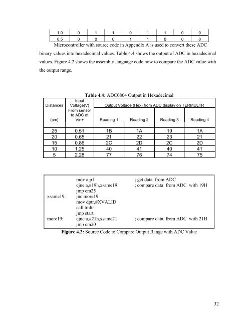
1.0 0 1 1 0 1 1 0 00.5 0 0 0 1 1 0 0 0Microcontroller with source code in Appendix A is used to convert these ADCbinary values into hexadecimal values. Table 4.4 shows the output of ADC in hexadecimalvalues. Figure 4.2 shows the assembly language code how to compare the ADC value withthe output range.Distances(cm)Table 4.4: ADC0804 Output in HexadecimalInputVoltage(V) Output Voltage (Hex) from ADC display on TERMULTRFrom sensorto ADC atVin+ Reading 1 Reading 2 Reading 3 Reading 425 0.51 1B 1A 19 1A20 0.65 21 22 23 2115 0.86 2C 2D 2C 2D10 1.25 40 41 40 415 2.28 77 76 74 75xsame19:mov a,p1cjne a,#19h,xsame19jmp cm25jnc more19mov dptr,#XVALIDcall tmltrjmp start; get data from ADC; compare data from ADC with 19Hmore19: cjne a,#21h,xsame21 ; compare data from ADC with 21Hjmp cm20Figure 4.2: Source Code to Compare Output Range with ADC Value32


