

CHAPTER 3 METHODOLOGY 3.1 Overview The Water Monitoring ...
CHAPTER 3 METHODOLOGY 3.1 Overview The Water Monitoring ...
CHAPTER 3 METHODOLOGY 3.1 Overview The Water Monitoring ...

You also want an ePaper? Increase the reach of your titles
YUMPU automatically turns print PDFs into web optimized ePapers that Google loves.
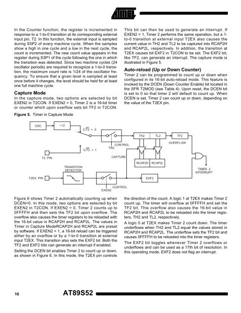
In the Counter function, the register is incremented inresponse to a 1-to-0 transition at its corresponding externalinput pin, T2. In this function, the external input is sampledduring S5P2 of every machine cycle. When the samplesshow a high in one cycle and a low in the next cycle, thecount is incremented. <strong>The</strong> new count value appears in theregister during S3P1 of the cycle following the one in whichthe transition was detected. Since two machine cycles (24oscillator periods) are required to recognize a 1-to-0 transition,the maximum count rate is 1/24 of the oscillator frequency.To ensure that a given level is sampled at leastonce before it changes, the level should be held for at leastone full machine cycle.Capture ModeIn the capture mode, two options are selected by bitEXEN2 in T2CON. If EXEN2 = 0, Timer 2 is a 16-bit timeror counter which upon overflow sets bit TF2 in T2CON.This bit can then be used to generate an interrupt. IfEXEN2 = 1, Timer 2 performs the same operation, but a 1-to-0 transition at external input T2EX also causes thecurrent value in TH2 and TL2 to be captured into RCAP2Hand RCAP2L, respectively. In addition, the transition atT2EX causes bit EXF2 in T2CON to be set. <strong>The</strong> EXF2 bit,like TF2, can generate an interrupt. <strong>The</strong> capture mode isillustrated in Figure 5.Auto-reload (Up or Down Counter)Timer 2 can be programmed to count up or down whenconfigured in its 16-bit auto-reload mode. This feature isinvoked by the DCEN (Down Counter Enable) bit located inthe SFR T2MOD (see Table 4). Upon reset, the DCEN bitis set to 0 so that timer 2 will default to count up. WhenDCEN is set, Timer 2 can count up or down, depending onthe value of the T2EX pin.Figure 5. Timer in Capture ModeOSC÷12C/T2 = 0C/T2 = 1CONTROLTR2TH2 TL2 TF2OVERFLOWT2 PINCAPTURETRANSITIONDETECTORRCAP2HRCAP2LTIMER 2INTERRUPTT2EX PINEXF2CONTROLEXEN2Figure 6 shows Timer 2 automatically counting up whenDCEN=0. In this mode, two options are selected by bitEXEN2 in T2CON. If EXEN2 = 0, Timer 2 counts up to0FFFFH and then sets the TF2 bit upon overflow. <strong>The</strong>overflow also causes the timer registers to be reloaded withthe 16-bit value in RCAP2H and RCAP2L. <strong>The</strong> values inTimer in Capture ModeRCAP2H and RCAP2L are presetby software. If EXEN2 = 1, a 16-bit reload can be triggeredeither by an overflow or by a 1-to-0 transition at externalinput T2EX. This transition also sets the EXF2 bit. Both theTF2 and EXF2 bits can generate an interrupt if enabled.Setting the DCEN bit enables Timer 2 to count up or down,as shown in Figure 6. In this mode, the T2EX pin controlsthe direction of the count. A logic 1 at T2EX makes Timer 2count up. <strong>The</strong> timer will overflow at 0FFFFH and set theTF2 bit. This overflow also causes the 16-bit value inRCAP2H and RCAP2L to be reloaded into the timer registers,TH2 and TL2, respectively.A logic 0 at T2EX makes Timer 2 count down. <strong>The</strong> timerunderflows when TH2 and TL2 equal the values stored inRCAP2H and RCAP2L. <strong>The</strong> underflow sets the TF2 bit andcauses 0FFFFH to be reloaded into the timer registers.<strong>The</strong> EXF2 bit toggles whenever Timer 2 overflows orunderflows and can be used as a 17th bit of resolution. Inthis operating mode, EXF2 does not flag an interrupt.10AT89S52


