

CHAPTER 3 METHODOLOGY 3.1 Overview The Water Monitoring ...
CHAPTER 3 METHODOLOGY 3.1 Overview The Water Monitoring ...
CHAPTER 3 METHODOLOGY 3.1 Overview The Water Monitoring ...

You also want an ePaper? Increase the reach of your titles
YUMPU automatically turns print PDFs into web optimized ePapers that Google loves.
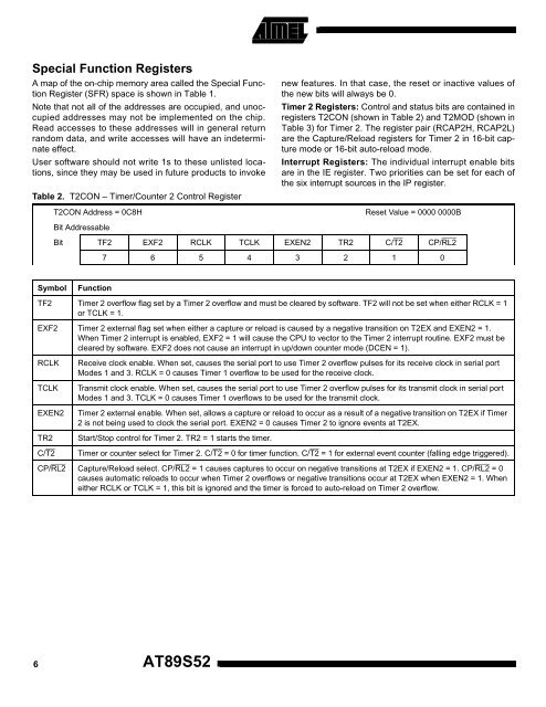
Special Function RegistersA map of the on-chip memory area called the Special FunctionRegister (SFR) space is shown in Table 1.Note that not all of the addresses are occupied, and unoccupiedaddresses may not be implemented on the chip.Read accesses to these addresses will in general returnrandom data, and write accesses will have an indeterminateeffect.User software should not write 1s to these unlisted locations,since they may be used in future products to invokeTable 2. T2CON – Timer/Counter 2 Control RegisterT2CON Address = 0C8Hnew features. In that case, the reset or inactive values ofthe new bits will always be 0.Timer 2 Registers: Control and status bits are contained inregisters T2CON (shown in Table 2) and T2MOD (shown inTable 3) for Timer 2. <strong>The</strong> register pair (RCAP2H, RCAP2L)are the Capture/Reload registers for Timer 2 in 16-bit capturemode or 16-bit auto-reload mode.Interrupt Registers: <strong>The</strong> individual interrupt enable bitsare in the IE register. Two priorities can be set for each ofthe six interrupt sources in the IP register.Reset Value = 0000 0000BBit AddressableBit TF2 EXF2 RCLK TCLK EXEN2 TR2 C/T2 CP/RL27 6 5 4 3 2 1 0SymbolFunctionTF2 Timer 2 overflow flag set by a Timer 2 overflow and must be cleared by software. TF2 will not be set when either RCLK = 1or TCLK = 1.EXF2 Timer 2 external flag set when either a capture or reload is caused by a negative transition on T2EX and EXEN2 = 1.When Timer 2 interrupt is enabled, EXF2 = 1 will cause the CPU to vector to the Timer 2 interrupt routine. EXF2 must becleared by software. EXF2 does not cause an interrupt in up/down counter mode (DCEN = 1).RCLKTCLKEXEN2TR2C/T2Receive clock enable. When set, causes the serial port to use Timer 2 overflow pulses for its receive clock in serial portModes 1 and 3. RCLK = 0 causes Timer 1 overflow to be used for the receive clock.Transmit clock enable. When set, causes the serial port to use Timer 2 overflow pulses for its transmit clock in serial portModes 1 and 3. TCLK = 0 causes Timer 1 overflows to be used for the transmit clock.Timer 2 external enable. When set, allows a capture or reload to occur as a result of a negative transition on T2EX if Timer2 is not being used to clock the serial port. EXEN2 = 0 causes Timer 2 to ignore events at T2EX.Start/Stop control for Timer 2. TR2 = 1 starts the timer.Timer or counter select for Timer 2. C/T2 = 0 for timer function. C/T2 = 1 for external event counter (falling edge triggered).CP/RL2 Capture/Reload select. CP/RL2 = 1 causes captures to occur on negative transitions at T2EX if EXEN2 = 1. CP/RL2 = 0causes automatic reloads to occur when Timer 2 overflows or negative transitions occur at T2EX when EXEN2 = 1. Wheneither RCLK or TCLK = 1, this bit is ignored and the timer is forced to auto-reload on Timer 2 overflow.6AT89S52


