

CHAPTER 3 METHODOLOGY 3.1 Overview The Water Monitoring ...
CHAPTER 3 METHODOLOGY 3.1 Overview The Water Monitoring ...
CHAPTER 3 METHODOLOGY 3.1 Overview The Water Monitoring ...

Create successful ePaper yourself
Turn your PDF publications into a flip-book with our unique Google optimized e-Paper software.
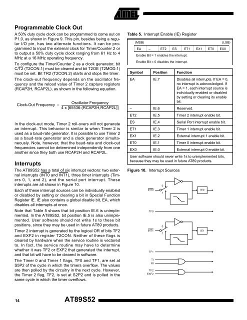
Programmable Clock OutA 50% duty cycle clock can be programmed to come out onP1.0, as shown in Figure 9. This pin, besides being a regularI/O pin, has two alternate functions. It can be programmedto input the external clock for Timer/Counter 2 orto output a 50% duty cycle clock ranging from 61 Hz to 4MHz at a 16 MHz operating frequency.To configure the Timer/Counter 2 as a clock generator, bitC/T2 (T2CON.1) must be cleared and bit T2OE (T2MOD.1)must be set. Bit TR2 (T2CON.2) starts and stops the timer.<strong>The</strong> clock-out frequency depends on the oscillator frequencyand the reload value of Timer 2 capture registers(RCAP2H, RCAP2L), as shown in the following equation.Clock-Out Frequency=Oscillator Frequency------------------------------------------------------------------------------------4 x [65536-(RCAP2H,RCAP2L)]Table 5. Interrupt Enable (IE) Register(MSB)EA – ET2 ES ET1 EX1 ET0 EX0Enable Bit = 1 enables the interrupt.Enable Bit = 0 disables the interrupt.Symbol Position Function(LSB)EA IE.7 Disables all interrupts. If EA = 0,no interrupt is acknowledged. IfEA = 1, each interrupt source isindividually enabled or disabledby setting or clearing its enablebit.– IE.6 Reserved.ET2 IE.5 Timer 2 interrupt enable bit.In the clock-out mode, Timer 2 roll-overs will not generatean interrupt. This behavior is similar to when Timer 2 isused as a baud-rate generator. It is possible to use Timer 2as a baud-rate generator and a clock generator simultaneously.Note, however, that the baud-rate and clock-outfrequencies cannot be determined independently from oneanother since they both use RCAP2H and RCAP2L.Interrupts<strong>The</strong> AT89S52 has a total of six interrupt vectors: two externalinterrupts (INT0 and INT1), three timer interrupts (Timers0, 1, and 2), and the serial port interrupt. <strong>The</strong>seinterrupts are all shown in Figure 10.Each of these interrupt sources can be individually enabledor disabled by setting or clearing a bit in Special FunctionRegister IE. IE also contains a global disable bit, EA, whichdisables all interrupts at once.Note that Table 5 shows that bit position IE.6 is unimplemented.In the AT89S52, bit position IE.5 is also unimplemented.User software should not write 1s to these bitpositions, since they may be used in future AT89 products.Timer 2 interrupt is generated by the logical OR of bits TF2and EXF2 in register T2CON. Neither of these flags iscleared by hardware when the service routine is vectoredto. In fact, the service routine may have to determinewhether it was TF2 or EXF2 that generated the interrupt,and that bit will have to be cleared in software.<strong>The</strong> Timer 0 and Timer 1 flags, TF0 and TF1, are set atS5P2 of the cycle in which the timers overflow. <strong>The</strong> valuesare then polled by the circuitry in the next cycle. However,the Timer 2 flag, TF2, is set at S2P2 and is polled in thesame cycle in which the timer overflows.ES IE.4 Serial Port interrupt enable bit.ET1 IE.3 Timer 1 interrupt enable bit.EX1 IE.2 External interrupt 1 enable bit.ET0 IE.1 Timer 0 interrupt enable bit.EX0 IE.0 External interrupt 0 enable bit.User software should never write 1s to unimplemented bits,because they may be used in future AT89 products.Figure 10. Interrupt SourcesINT0TF0INT1TF1TIRITF2EXF20101IE0IE114AT89S52


