

CHAPTER 3 METHODOLOGY 3.1 Overview The Water Monitoring ...
CHAPTER 3 METHODOLOGY 3.1 Overview The Water Monitoring ...
CHAPTER 3 METHODOLOGY 3.1 Overview The Water Monitoring ...

You also want an ePaper? Increase the reach of your titles
YUMPU automatically turns print PDFs into web optimized ePapers that Google loves.
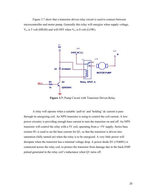
Figure 3.7 show that a transistor driven relay circuit is used to connect betweenmicrocontroller and motor pump. Generally this relay will energize when supply voltage,V in is 5 volt (HIGH) and will OFF when V in is 0 volt (LOW).U25VU24240V AC (L)U27NU1U18D1D1N4001NCCOMNOA1 2MOTOR PUMPBP2.1R1Q1Relay_SPDT_b1kQ2N3904Figure 3.7: Pump Circuit with Transistor Driven RelayA relay will operate when a suitable ‘pull-in’ and ‘holding’ dc current is passthrough its energizing coil. An NPN transistor is using to control the coil current. A lowpowercircuitry is providing enough base current to turn the transistor on and off. An NPNtransistor will control the relay with a 5V coil, operating from a +5V supply. Series baseresistor R1 is used to set the base current for Q1, so that the transistor is driven intosaturation (fully turned on) when the relay is to be energized. A very little power willdissipate when the transistor has a minimal voltage drop. A power diode D1 (1N4001) isconnected across the relay coil, to protect the transistor from damage due to the back-EMFpulsed generated in the relay coil’s inductance when Q1 turns off.20


