Programmable Clock OutA 50% duty cycle clock can be programmed to come out onP1.0, as shown in Figure 9. This pin, besides being a regularI/O pin, has two alternate functions. It can be programmedto input the external clock for Timer/Counter 2 orto output a 50% duty cycle clock ranging from 61 Hz to 4MHz at a 16 MHz operating frequency.To configure the Timer/Counter 2 as a clock generator, bitC/T2 (T2CON.1) must be cleared and bit T2OE (T2MOD.1)must be set. Bit TR2 (T2CON.2) starts and stops the timer.<strong>The</strong> clock-out frequency depends on the oscillator frequencyand the reload value of Timer 2 capture registers(RCAP2H, RCAP2L), as shown in the following equation.Clock-Out Frequency=Oscillator Frequency------------------------------------------------------------------------------------4 x [65536-(RCAP2H,RCAP2L)]Table 5. Interrupt Enable (IE) Register(MSB)EA – ET2 ES ET1 EX1 ET0 EX0Enable Bit = 1 enables the interrupt.Enable Bit = 0 disables the interrupt.Symbol Position Function(LSB)EA IE.7 Disables all interrupts. If EA = 0,no interrupt is acknowledged. IfEA = 1, each interrupt source isindividually enabled or disabledby setting or clearing its enablebit.– IE.6 Reserved.ET2 IE.5 Timer 2 interrupt enable bit.In the clock-out mode, Timer 2 roll-overs will not generatean interrupt. This behavior is similar to when Timer 2 isused as a baud-rate generator. It is possible to use Timer 2as a baud-rate generator and a clock generator simultaneously.Note, however, that the baud-rate and clock-outfrequencies cannot be determined independently from oneanother since they both use RCAP2H and RCAP2L.Interrupts<strong>The</strong> AT89S52 has a total of six interrupt vectors: two externalinterrupts (INT0 and INT1), three timer interrupts (Timers0, 1, and 2), and the serial port interrupt. <strong>The</strong>seinterrupts are all shown in Figure 10.Each of these interrupt sources can be individually enabledor disabled by setting or clearing a bit in Special FunctionRegister IE. IE also contains a global disable bit, EA, whichdisables all interrupts at once.Note that Table 5 shows that bit position IE.6 is unimplemented.In the AT89S52, bit position IE.5 is also unimplemented.User software should not write 1s to these bitpositions, since they may be used in future AT89 products.Timer 2 interrupt is generated by the logical OR of bits TF2and EXF2 in register T2CON. Neither of these flags iscleared by hardware when the service routine is vectoredto. In fact, the service routine may have to determinewhether it was TF2 or EXF2 that generated the interrupt,and that bit will have to be cleared in software.<strong>The</strong> Timer 0 and Timer 1 flags, TF0 and TF1, are set atS5P2 of the cycle in which the timers overflow. <strong>The</strong> valuesare then polled by the circuitry in the next cycle. However,the Timer 2 flag, TF2, is set at S2P2 and is polled in thesame cycle in which the timer overflows.ES IE.4 Serial Port interrupt enable bit.ET1 IE.3 Timer 1 interrupt enable bit.EX1 IE.2 External interrupt 1 enable bit.ET0 IE.1 Timer 0 interrupt enable bit.EX0 IE.0 External interrupt 0 enable bit.User software should never write 1s to unimplemented bits,because they may be used in future AT89 products.Figure 10. Interrupt SourcesINT0TF0INT1TF1TIRITF2EXF20101IE0IE114AT89S52
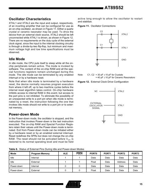
AT89S52Oscillator CharacteristicsXTAL1 and XTAL2 are the input and output, respectively,of an inverting amplifier that can be configured for use asan on-chip oscillator, as shown in Figure 11. Either a quartzcrystal or ceramic resonator may be used. To drive thedevice from an external clock source, XTAL2 should be leftunconnected while XTAL1 is driven, as shown in Figure 12.<strong>The</strong>re are no requirements on the duty cycle of the externalclock signal, since the input to the internal clocking circuitryis through a divide-by-two flip-flop, but minimum and maximumvoltage high and low time specifications must beobserved.Idle ModeIn idle mode, the CPU puts itself to sleep while all the onchipperipherals remain active. <strong>The</strong> mode is invoked bysoftware. <strong>The</strong> content of the on-chip RAM and all the specialfunctions registers remain unchanged during thismode. <strong>The</strong> idle mode can be terminated by any enabledinterrupt or by a hardware reset.Note that when idle mode is terminated by a hardwarereset, the device normally resumes program executionfrom where it left off, up to two machine cycles before theinternal reset algorithm takes control. On-chip hardwareinhibits access to internal RAM in this event, but access tothe port pins is not inhibited. To eliminate the possibility ofan unexpected write to a port pin when idle mode is terminatedby a reset, the instruction following the one thatinvokes idle mode should not write to a port pin or to externalmemory.Power-down ModeIn the Power-down mode, the oscillator is stopped, and theinstruction that invokes Power-down is the last instructionexecuted. <strong>The</strong> on-chip RAM and Special Function Registersretain their values until the Power-down mode is terminated.Exit from Power-down mode can be initiated eitherby a hardware reset or by an enabled external interrupt.Reset redefines the SFRs but does not change the on-chipRAM. <strong>The</strong> reset should not be activated before V CC isrestored to its normal operating level and must be heldactive long enough to allow the oscillator to restartand stabilize.Figure 11. Oscillator ConnectionsC2C1XTAL2XTAL1GNDNote: C1, C2 = 30 pF ± 10 pF for Crystals= 40 pF ± 10 pF for Ceramic ResonatorsFigure 12. External Clock Drive ConfigurationNCEXTERNALOSCILLATORSIGNALXTAL2XTAL1GNDTable 6. Status of External Pins During Idle and Power-down ModesMode Program Memory ALE PSEN PORT0 PORT1 PORT2 PORT3Idle Internal 1 1 Data Data Data DataIdle External 1 1 Float Data Address DataPower-down Internal 0 0 Data Data Data DataPower-down External 0 0 Float Data Data Data15
- Page 1 and 2:
CHAPTER 3METHODOLOGY3.1 OverviewThe
- Page 3 and 4: 3.2.2 Analog To Digital Conversion
- Page 5 and 6: Figure 3.5: Source Code for Convers
- Page 7 and 8: 3.2.4 Water Monitoring System Circu
- Page 9 and 10: 3.3 Programming.Programming is the
- Page 11 and 12: ISP flash programmer in Figure 3.11
- Page 13 and 14: The Visual Basic program will start
- Page 15 and 16: Distance(cm)ReadingVoltage Trial1 (
- Page 17 and 18: 4.2 Signal ConversionA sensor has s
- Page 19 and 20: 4.3 User InterfaceBased on Table 4.
- Page 21 and 22: Hardware DesignBasically, the const
- Page 23 and 24: CHAPTER 5CONCLUSION5.1 SummaryWater
- Page 25 and 26: This project can be expanded by usi
- Page 27 and 28: APPENDICES41
- Page 29 and 30: cjne a,volt,xsamejmp startxsame:mov
- Page 31 and 32: xsame19:jnc more19mov dptr,#XVALIDc
- Page 33 and 34: etrx:jnb ri,$clr rimov a,sbufretdel
- Page 35 and 36: ElseShape8.FillColor = vbWhiteEnd I
- Page 37 and 38: Private Sub Timer3_Timer()Label3.Ca
- Page 39 and 40: APPENDIX EData Sheet AT89S5253
- Page 41 and 42: Features• Compatible with MCS-51
- Page 43 and 44: AT89S52Block DiagramP0.0 - P0.7P2.0
- Page 45 and 46: AT89S52weakly pulled high. Setting
- Page 47 and 48: AT89S52Table 3a. AUXR: Auxiliary Re
- Page 49 and 50: AT89S52Watchdog Timer(One-time Enab
- Page 51 and 52: AT89S52Figure 6. Timer 2 Auto Reloa
- Page 53: AT89S52Baud Rate GeneratorTimer 2 i
- Page 57 and 58: AT89S52frequency should be less tha
- Page 59 and 60: Figure 15. Flash Programming and Ve
- Page 61 and 62: AT89S52Table 9. Serial Programming
- Page 63 and 64: AT89S52Absolute Maximum Ratings*Ope
- Page 65 and 66: AT89S52External Program Memory Read
- Page 67 and 68: AT89S52Serial Port Timing: Shift Re
- Page 69 and 70: Packaging Information44A, 44-lead,
- Page 71 and 72: August 1997SemiconductorADC0802, AD
- Page 73 and 74: ADC0802, ADC0803, ADC0804Absolute M
- Page 75 and 76: ADC0802, ADC0803, ADC0804Electrical
- Page 77 and 78: ADC0802, ADC0803, ADC0804Typical Pe
- Page 79 and 80: ADC0802, ADC0803, ADC0804The device
- Page 81 and 82: ADC0802, ADC0803, ADC0804V IN ±5VR
- Page 83 and 84: ADC0802, ADC0803, ADC0804Figures 19
- Page 85 and 86: ADC0802, ADC0803, ADC0804IRQ (4)†