ncr/doc/Old Models/Technical Manuals/7453_... - Alsys Data
ncr/doc/Old Models/Technical Manuals/7453_... - Alsys Data
ncr/doc/Old Models/Technical Manuals/7453_... - Alsys Data
- No tags were found...

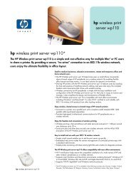
You also want an ePaper? Increase the reach of your titles
YUMPU automatically turns print PDFs into web optimized ePapers that Google loves.
4-60 Chapter 4: Hardware ServiceHardware Installation1. Set S1, S2, JP1, and JP3 switches and jumpers.• S1 sets the base address for the Serial Board.• S2 sets the base address for the Serial Board and the specialcontrol registers – Status Register and Interrupt Mask Register.• JP1 sets the interrupt level.• JP3 sets the operating frequency.The following are default settings. If alterations are made in theconfiguration, ensure that there are no conflicts with the I/Oaddress and interrupt levels of other devices. These settingscorrespond to an I/O address range of 0x240 – 0x27F.8-Port RS-232 Board Settings (with 586 Main processor board)S1 1 2 3 4 5 6 7 8ON ON ON ON ON ON OFF ONS2 1 2 3 4JP1 5ON OFF ON OFFJP31.8432 MHzThese following settings correspond to an I/O address range of0x440 to 0x47F.8-Port RS-232 Board Settings (with 686 and all other Main processor boards)S1 1 2 3 4 5 6 7 8ON ON ON ON ON OFF ON ONS2 1 2 3 4JP1 5ON OFF ON OFFJP31.8432 MHz