

Rosemount 3051S Electronic Remote Sensors - Emerson Process ...
Rosemount 3051S Electronic Remote Sensors - Emerson Process ...
Rosemount 3051S Electronic Remote Sensors - Emerson Process ...

Create successful ePaper yourself
Turn your PDF publications into a flip-book with our unique Google optimized e-Paper software.
<strong>Rosemount</strong> <strong>3051S</strong> ERS System<br />
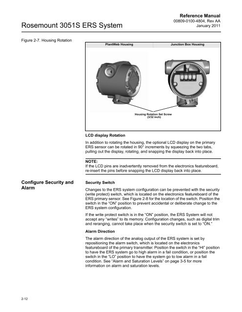
Figure 2-7. Housing Rotation<br />
Configure Security and<br />
Alarm<br />
2-12<br />
Reference Manual<br />
00809-0100-4804, Rev AA<br />
January 2011<br />
PlantWeb Housing Junction Box Housing<br />
Housing Rotation Set Screw<br />
(3/32 inch)<br />
LCD display Rotation<br />
In addition to rotating the housing, the optional LCD display on the primary<br />
ERS sensor can be rotated in 90° increments by squeezing the two tabs,<br />
pulling out the display, rotating, and snapping the display back into place.<br />
NOTE:<br />
If the LCD pins are inadvertently removed from the electronics featureboard,<br />
re-insert the pins before snapping the LCD display back into place.<br />
Security Switch<br />
Changes to the ERS system configuration can be prevented with the security<br />
(write protect) switch, which is located on the electronics featureboard of the<br />
ERS primary sensor. See Figure 2-8 for the location of the switch. Position the<br />
switch in the “ON” position to prevent accidental or deliberate change to the<br />
ERS system configuration.<br />
If the write protect switch is in the “ON” position, the ERS System will not<br />
accept any “writes” to its memory. Configuration changes, such as digital trim<br />
and reranging, cannot take place when the security switch is set to “ON.”<br />
Alarm Direction<br />
The alarm direction of the analog output of the ERS system is set by<br />
repositioning the alarm switch, which is located on the electronics<br />
featureboard of the primary transmitter. Position the switch in the “HI” position<br />
to have the ERS system go to high alarm in a fail condition, or position the<br />
switch in the “LO” position to have the system go to low alarm in a fail<br />
condition. See “Alarm and Saturation Levels” on page 3-5 for more<br />
information on alarm and saturation levels.


