

Rosemount 3051S Electronic Remote Sensors - Emerson Process ...
Rosemount 3051S Electronic Remote Sensors - Emerson Process ...
Rosemount 3051S Electronic Remote Sensors - Emerson Process ...

You also want an ePaper? Increase the reach of your titles
YUMPU automatically turns print PDFs into web optimized ePapers that Google loves.
<strong>Rosemount</strong> <strong>3051S</strong> ERS System<br />
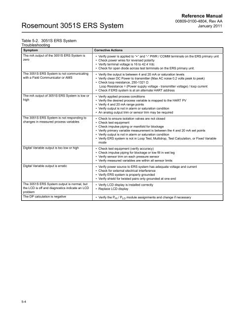
Table 5-2. <strong>3051S</strong> ERS System<br />
Troubleshooting<br />
Symptom Corrective Actions<br />
The mA output of the <strong>3051S</strong> ERS System is<br />
zero<br />
The <strong>3051S</strong> ERS System is not communicating<br />
with a Field Communicator or AMS<br />
The mA output of <strong>3051S</strong> ERS System is low or<br />
high<br />
The <strong>3051S</strong> ERS System is not responding to<br />
changes in measured process variables<br />
5-4<br />
Reference Manual<br />
00809-0100-4804, Rev AA<br />
January 2011<br />
• Verify power is applied to “+” and “-” PWR / COMM terminals on the ERS primary unit<br />
• Check power wires for reversed polarity<br />
• Verify terminal voltage is 16 to 42.4 Vdc<br />
• Check for open diode across test terminals on the ERS primary unit.<br />
• Verify the output is between 4 and 20 mA or saturation levels<br />
• Verify clean DC Power to transmitter (Max AC noise 0.2 volts peak to peak)<br />
• Check loop resistance, 250-1321 Ω<br />
Loop Resistance = (Power supply voltage - transmitter voltage) / loop current<br />
• Check if ERS system is at an alternate HART address<br />
• Verify applied process conditions<br />
• Verify the desired process variable is mapped to the HART PV<br />
• Verify 4 and 20 mA range points<br />
• Verify output is not in alarm or saturation condition<br />
• An analog output trim or sensor trim may be required<br />
• Check to ensure isolation valves are not closed<br />
• Check test equipment<br />
• Check impulse piping or manifold for blockage<br />
• Verify primary variable measurement is between the 4 and 20 mA set points<br />
• Verify output is not in alarm or saturation condition<br />
• Verify ERS system is not in Loop Test, Multidrop, Test Calculation, or Fixed Variable<br />
mode<br />
Digital Variable output is too low or high • Check test equipment (verify accuracy)<br />
• Check impulse piping for blockage or low fill in wet leg<br />
• Verify sensor trim on each pressure sensor<br />
• Verify measured variables are within all sensor limits<br />
Digital Variable output is erratic • Verify power source to ERS system has adequate voltage and current<br />
• Check for external electrical interference<br />
• Verify ERS system is properly grounded<br />
• Verify shield for twisted pairs only grounded at one end<br />
The <strong>3051S</strong> ERS System output is normal, but<br />
the LCD is off and diagnostics indicate an LCD<br />
problem<br />
• Verify LCD display is installed correctly<br />
• Replace LCD display<br />
The DP calculation is negative • Verify the P HI / P LO module assignments and change if necessary


