

VS1033 - MP3/AAC/WMA/MIDI AUDIO CODEC - VLSI Solution
VS1033 - MP3/AAC/WMA/MIDI AUDIO CODEC - VLSI Solution
VS1033 - MP3/AAC/WMA/MIDI AUDIO CODEC - VLSI Solution

You also want an ePaper? Increase the reach of your titles
YUMPU automatically turns print PDFs into web optimized ePapers that Google loves.
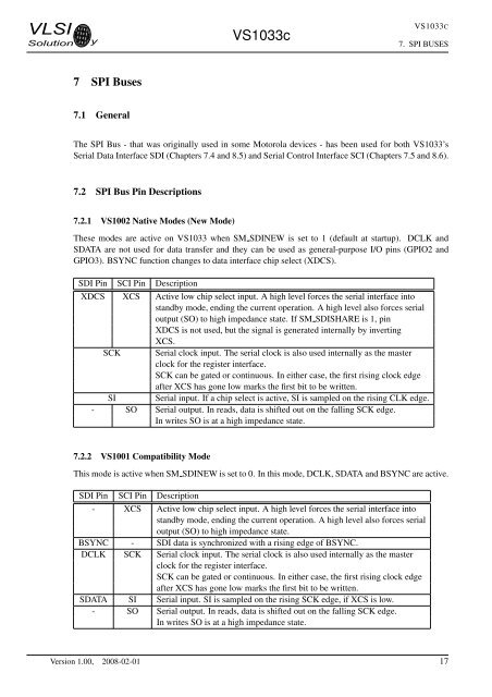
<strong>VLSI</strong><strong>Solution</strong> y<strong>VS1033</strong>c<strong>VS1033</strong>C7. SPI BUSES7 SPI Buses7.1 GeneralThe SPI Bus - that was originally used in some Motorola devices - has been used for both <strong>VS1033</strong>’sSerial Data Interface SDI (Chapters 7.4 and 8.5) and Serial Control Interface SCI (Chapters 7.5 and 8.6).7.2 SPI Bus Pin Descriptions7.2.1 VS1002 Native Modes (New Mode)These modes are active on <strong>VS1033</strong> when SM SDINEW is set to 1 (default at startup). DCLK andSDATA are not used for data transfer and they can be used as general-purpose I/O pins (GPIO2 andGPIO3). BSYNC function changes to data interface chip select (XDCS).SDI Pin SCI Pin DescriptionXDCS XCS Active low chip select input. A high level forces the serial interface intostandby mode, ending the current operation. A high level also forces serialoutput (SO) to high impedance state. If SM SDISHARE is 1, pinXDCS is not used, but the signal is generated internally by invertingXCS.SCK Serial clock input. The serial clock is also used internally as the masterclock for the register interface.SCK can be gated or continuous. In either case, the first rising clock edgeafter XCS has gone low marks the first bit to be written.SI Serial input. If a chip select is active, SI is sampled on the rising CLK edge.- SO Serial output. In reads, data is shifted out on the falling SCK edge.In writes SO is at a high impedance state.7.2.2 VS1001 Compatibility ModeThis mode is active when SM SDINEW is set to 0. In this mode, DCLK, SDATA and BSYNC are active.SDI Pin SCI Pin Description- XCS Active low chip select input. A high level forces the serial interface intostandby mode, ending the current operation. A high level also forces serialoutput (SO) to high impedance state.BSYNC - SDI data is synchronized with a rising edge of BSYNC.DCLK SCK Serial clock input. The serial clock is also used internally as the masterclock for the register interface.SCK can be gated or continuous. In either case, the first rising clock edgeafter XCS has gone low marks the first bit to be written.SDATA SI Serial input. SI is sampled on the rising SCK edge, if XCS is low.- SO Serial output. In reads, data is shifted out on the falling SCK edge.In writes SO is at a high impedance state.Version 1.00, 2008-02-01 17


