

VS1033 - MP3/AAC/WMA/MIDI AUDIO CODEC - VLSI Solution
VS1033 - MP3/AAC/WMA/MIDI AUDIO CODEC - VLSI Solution
VS1033 - MP3/AAC/WMA/MIDI AUDIO CODEC - VLSI Solution

Create successful ePaper yourself
Turn your PDF publications into a flip-book with our unique Google optimized e-Paper software.
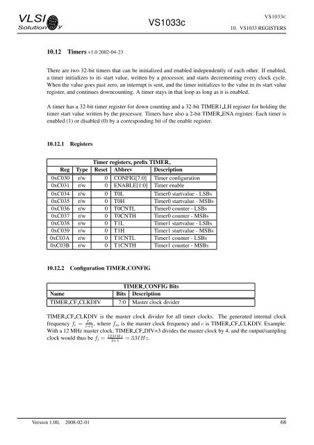
<strong>VLSI</strong><strong>Solution</strong> y<strong>VS1033</strong>c<strong>VS1033</strong>C10. <strong>VS1033</strong> REGISTERS10.12 Timers v1.0 2002-04-23There are two 32-bit timers that can be initialized and enabled independently of each other. If enabled,a timer initializes to its start value, written by a processor, and starts decrementing every clock cycle.When the value goes past zero, an interrupt is sent, and the timer initializes to the value in its start valueregister, and continues downcounting. A timer stays in that loop as long as it is enabled.A timer has a 32-bit timer register for down counting and a 32-bit TIMER1 LH register for holding thetimer start value written by the processor. Timers have also a 2-bit TIMER ENA register. Each timer isenabled (1) or disabled (0) by a corresponding bit of the enable register.10.12.1 RegistersTimer registers, prefix TIMERReg Type Reset Abbrev Description0xC030 r/w 0 CONFIG[7:0] Timer configuration0xC031 r/w 0 ENABLE[1:0] Timer enable0xC034 r/w 0 T0L Timer0 startvalue - LSBs0xC035 r/w 0 T0H Timer0 startvalue - MSBs0xC036 r/w 0 T0CNTL Timer0 counter - LSBs0xC037 r/w 0 T0CNTH Timer0 counter - MSBs0xC038 r/w 0 T1L Timer1 startvalue - LSBs0xC039 r/w 0 T1H Timer1 startvalue - MSBs0xC03A r/w 0 T1CNTL Timer1 counter - LSBs0xC03B r/w 0 T1CNTH Timer1 counter - MSBs10.12.2 Configuration TIMER CONFIGTIMER CONFIG BitsName Bits DescriptionTIMER CF CLKDIV 7:0 Master clock dividerTIMER CF CLKDIV is the master clock divider for all timer clocks. The generated internal clockfrequency f i = fmc+1 , where f m is the master clock frequency and c is TIMER CF CLKDIV. Example:With a 12 MHz master clock, TIMER CF DIV=3 divides the master clock by 4, and the output/samplingclock would thus be f i = 12MHz3+1= 3MHz.Version 1.00, 2008-02-01 68


