

VS1033 - MP3/AAC/WMA/MIDI AUDIO CODEC - VLSI Solution
VS1033 - MP3/AAC/WMA/MIDI AUDIO CODEC - VLSI Solution
VS1033 - MP3/AAC/WMA/MIDI AUDIO CODEC - VLSI Solution

You also want an ePaper? Increase the reach of your titles
YUMPU automatically turns print PDFs into web optimized ePapers that Google loves.
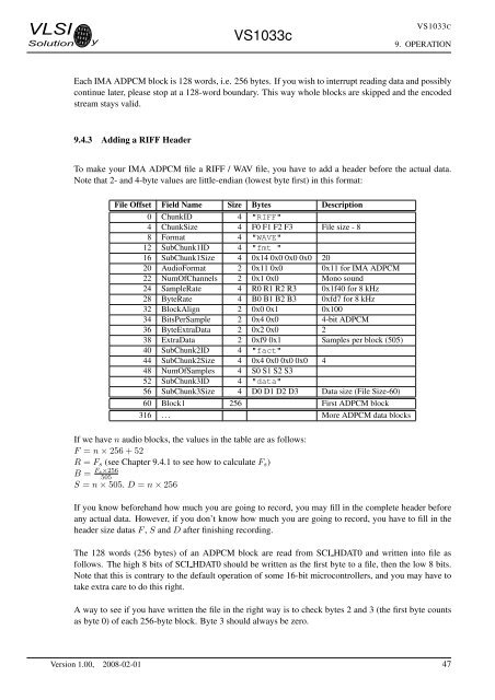
<strong>VLSI</strong><strong>Solution</strong> y<strong>VS1033</strong>c<strong>VS1033</strong>C9. OPERATIONEach IMA ADPCM block is 128 words, i.e. 256 bytes. If you wish to interrupt reading data and possiblycontinue later, please stop at a 128-word boundary. This way whole blocks are skipped and the encodedstream stays valid.9.4.3 Adding a RIFF HeaderTo make your IMA ADPCM file a RIFF / WAV file, you have to add a header before the actual data.Note that 2- and 4-byte values are little-endian (lowest byte first) in this format:File Offset Field Name Size Bytes Description0 ChunkID 4 "RIFF"4 ChunkSize 4 F0 F1 F2 F3 File size - 88 Format 4 "WAVE"12 SubChunk1ID 4 "fmt "16 SubChunk1Size 4 0x14 0x0 0x0 0x0 2020 AudioFormat 2 0x11 0x0 0x11 for IMA ADPCM22 NumOfChannels 2 0x1 0x0 Mono sound24 SampleRate 4 R0 R1 R2 R3 0x1f40 for 8 kHz28 ByteRate 4 B0 B1 B2 B3 0xfd7 for 8 kHz32 BlockAlign 2 0x0 0x1 0x10034 BitsPerSample 2 0x4 0x0 4-bit ADPCM36 ByteExtraData 2 0x2 0x0 238 ExtraData 2 0xf9 0x1 Samples per block (505)40 SubChunk2ID 4 "fact"44 SubChunk2Size 4 0x4 0x0 0x0 0x0 448 NumOfSamples 4 S0 S1 S2 S352 SubChunk3ID 4 "data"56 SubChunk3Size 4 D0 D1 D2 D3 Data size (File Size-60)60 Block1 256 First ADPCM block316 . . . More ADPCM data blocksIf we have n audio blocks, the values in the table are as follows:F = n × 256 + 52R = F s (see Chapter 9.4.1 to see how to calculate F s )B = Fs×256505S = n × 505. D = n × 256If you know beforehand how much you are going to record, you may fill in the complete header beforeany actual data. However, if you don’t know how much you are going to record, you have to fill in theheader size datas F , S and D after finishing recording.The 128 words (256 bytes) of an ADPCM block are read from SCI HDAT0 and written into file asfollows. The high 8 bits of SCI HDAT0 should be written as the first byte to a file, then the low 8 bits.Note that this is contrary to the default operation of some 16-bit microcontrollers, and you may have totake extra care to do this right.A way to see if you have written the file in the right way is to check bytes 2 and 3 (the first byte countsas byte 0) of each 256-byte block. Byte 3 should always be zero.Version 1.00, 2008-02-01 47


