

VS1033 - MP3/AAC/WMA/MIDI AUDIO CODEC - VLSI Solution
VS1033 - MP3/AAC/WMA/MIDI AUDIO CODEC - VLSI Solution
VS1033 - MP3/AAC/WMA/MIDI AUDIO CODEC - VLSI Solution

You also want an ePaper? Increase the reach of your titles
YUMPU automatically turns print PDFs into web optimized ePapers that Google loves.
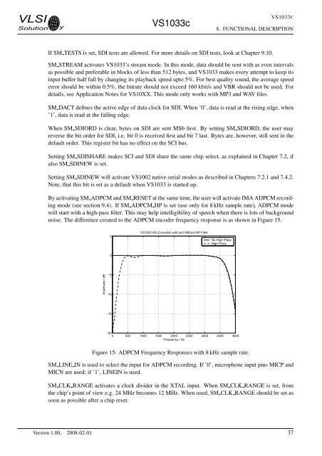
<strong>VLSI</strong><strong>Solution</strong> y<strong>VS1033</strong>c<strong>VS1033</strong>C8. FUNCTIONAL DESCRIPTIONIf SM TESTS is set, SDI tests are allowed. For more details on SDI tests, look at Chapter 9.10.SM STREAM activates <strong>VS1033</strong>’s stream mode. In this mode, data should be sent with as even intervalsas possible and preferable in blocks of less than 512 bytes, and <strong>VS1033</strong> makes every attempt to keep itsinput buffer half full by changing its playback speed upto 5%. For best quality sound, the average speederror should be within 0.5%, the bitrate should not exceed 160 kbit/s and VBR should not be used. Fordetails, see Application Notes for VS10XX. This mode only works with <strong>MP3</strong> and WAV files.SM DACT defines the active edge of data clock for SDI. When ’0’, data is read at the rising edge, when’1’, data is read at the falling edge.When SM SDIORD is clear, bytes on SDI are sent MSb first. By setting SM SDIORD, the user mayreverse the bit order for SDI, i.e. bit 0 is received first and bit 7 last. Bytes are, however, still sent in thedefault order. This register bit has no effect on the SCI bus.Setting SM SDISHARE makes SCI and SDI share the same chip select, as explained in Chapter 7.2, ifalso SM SDINEW is set.Setting SM SDINEW will activate VS1002 native serial modes as described in Chapters 7.2.1 and 7.4.2.Note, that this bit is set as a default when <strong>VS1033</strong> is started up.By activating SM ADPCM and SM RESET at the same time, the user will activate IMA ADPCM recordingmode (see section 9.4). If SM ADPCM HP is set (use only for 8 kHz sample rate), ADPCM modewill start with a high-pass filter. This may help intelligibility of speech when there is lots of backgroundnoise. The difference created to the ADPCM encoder frequency response is as shown in Figure 15.5VS1023 AD Converter with and Without HP FilterNo High−PassHigh−Pass0Amplitude / dB−5−10−15−200 500 1000 1500 2000 2500 3000 3500 4000Frequency / HzFigure 15: ADPCM Frequency Responses with 8 kHz sample rate.SM LINE IN is used to select the input for ADPCM recording. If ’0’, microphone input pins MICP andMICN are used; if ’1’, LINEIN is used.SM CLK RANGE activates a clock divider in the XTAL input. When SM CLK RANGE is set, fromthe chip’s point of view e.g. 24 MHz becomes 12 MHz. When used, SM CLK RANGE should be set assoon as possible after a chip reset.Version 1.00, 2008-02-01 37


